

Method for locating tire condition sensing apparatuses
- Summary
- Abstract
- Description
- Claims
- Application Information
AI Technical Summary
Benefits of technology
Problems solved by technology
Method used
Image

Examples
Embodiment Construction
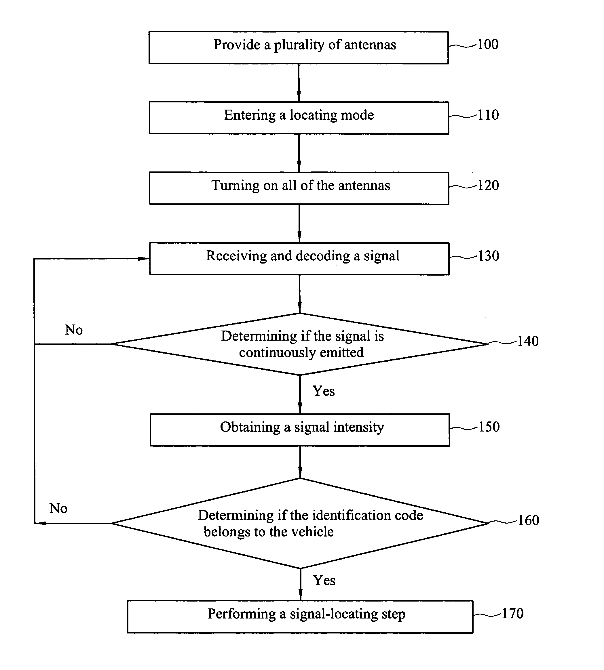
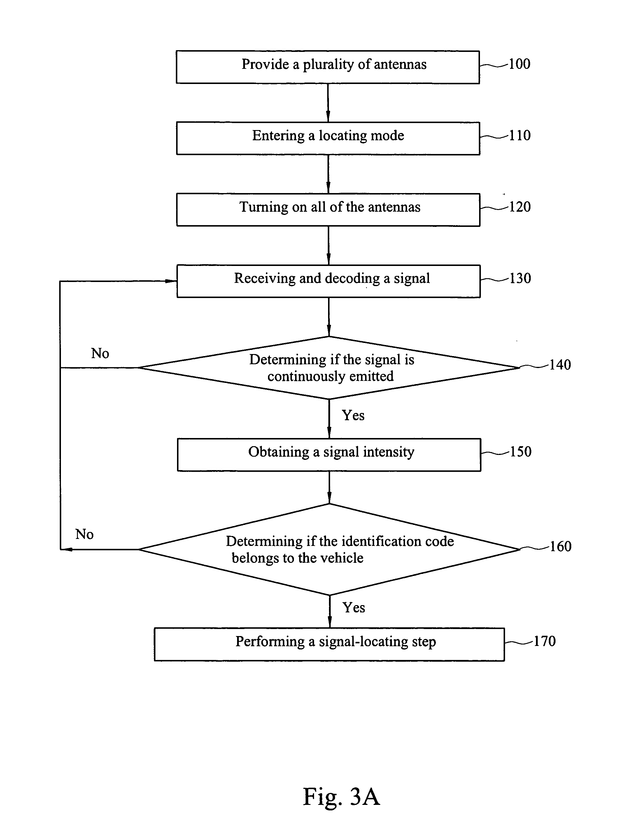
[0017] The present invention is featured in rapidly turning on / off antennas in turns and obtaining a plurality of signal intensity changes when it is ascertained that a tire condition sensing apparatus is emitting a signal, wherein the antenna generating a maximum value of those signal intensity changes is located at the position to which the tire condition sensing apparatus emitting the signal is corresponding.
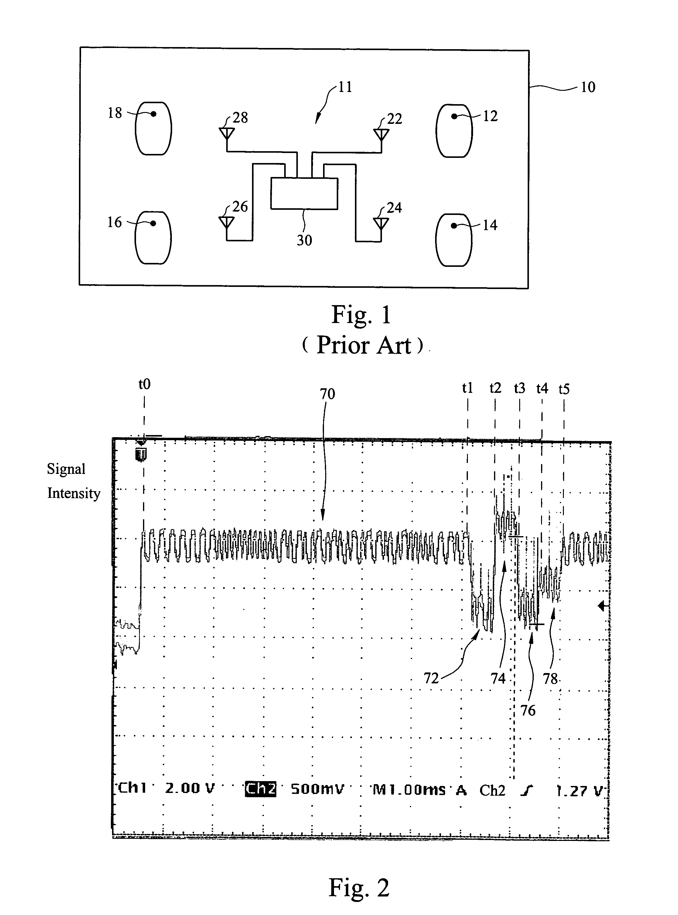
[0018] The present invention can be applied to the tire condition sensing system as shown in FIG. 1. Hereinafter, FIG. 1 is merely used for conveniently explaining the method of the present invention for locating the tire condition sensing apparatuses, and yet the present invention is not limited thereto. The present invention is applicable to any vehicle (such as cars, motorcycles, etc.) having any number of tires (including spare tires).
[0019]FIG. 2 is a schematic diagram showing a signal curve according to the method recited in an embodiment of the present invention for ...
PUM
 Abstract
Description
Claims
Application Information