Guided travel control method and control apparatus for unmanned vehicle

a technology for unmanned vehicles and control apparatuses, applied in process and machine control, distance measurement, instruments, etc., can solve the problems of reducing operation efficiency, requiring significant time, effort and skills, and unable to correct the aforementioned shi

Inactive Publication Date: 2008-05-08
KOMATSU LTD
View PDF3 Cites 27 Cited by
  • Summary
  • Abstract
  • Description
  • Claims
  • Application Information

AI Technical Summary

Benefits of technology

[0083]The effect obtained with the sixth invention is

Problems solved by technology

Therefore, with the method of Conventional Technology 1 by which teaching data are acquired by actually traveling along each traveling course till each target earth unloading point is reached, the teaching operation requires significant time, efforts, and skills and greatly decreases the operation efficiency.
Further, due to control errors in guided traveling control (computation processing) and errors caused by slip or the like, a shift occurs between the teaching data relating to the traveling course that was determined in advance and the actual travel trajectory of the unmanned vehicle 10 along the traveling course.
In particular, in a location where the unmanned vehicle 10 makes a sharp turn, max

Method used


Image

  • Guided travel control method and control apparatus for unmanned vehicle
  • Guided travel control method and control apparatus for unmanned vehicle
  • Guided travel control method and control apparatus for unmanned vehicle

Examples


first embodiment

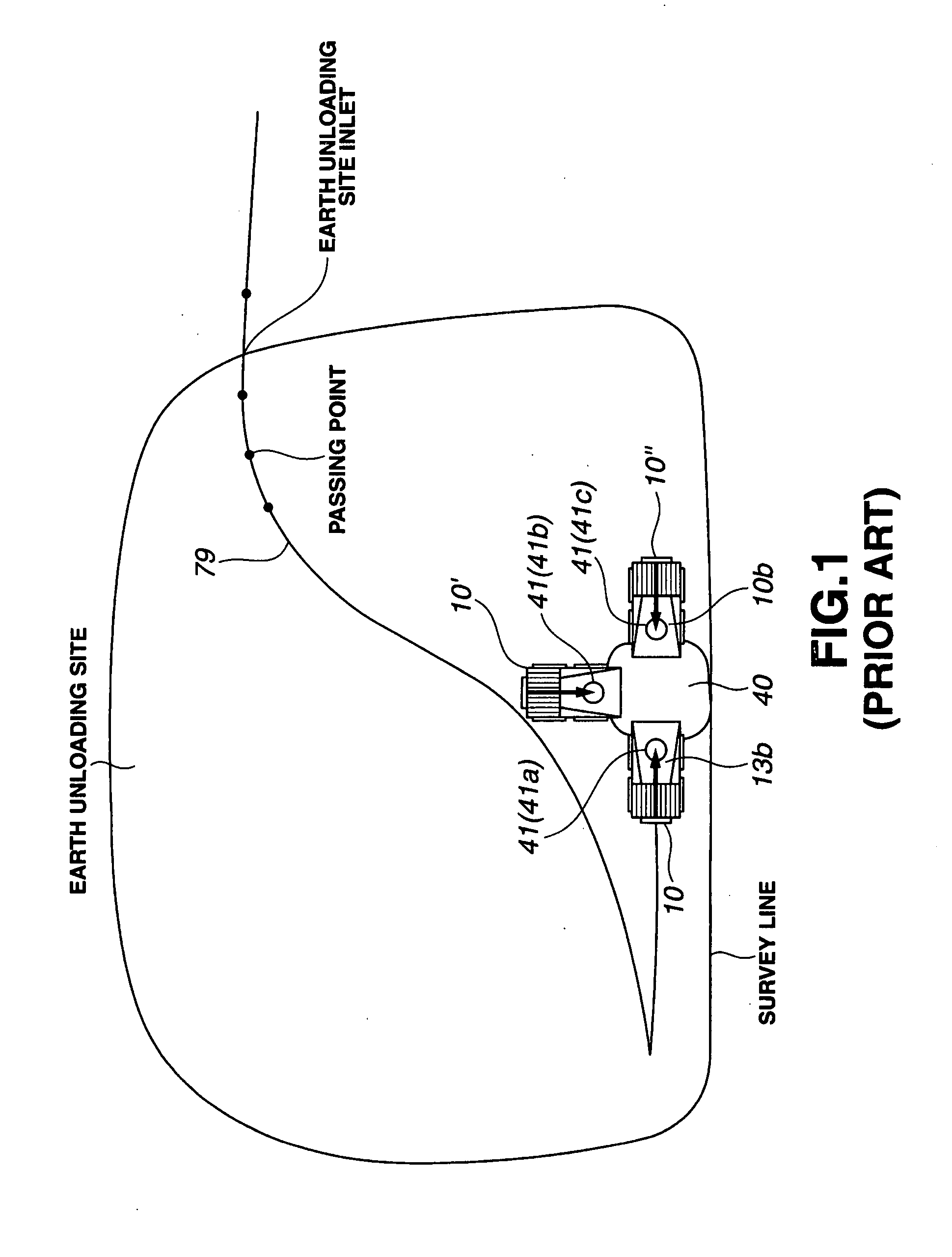
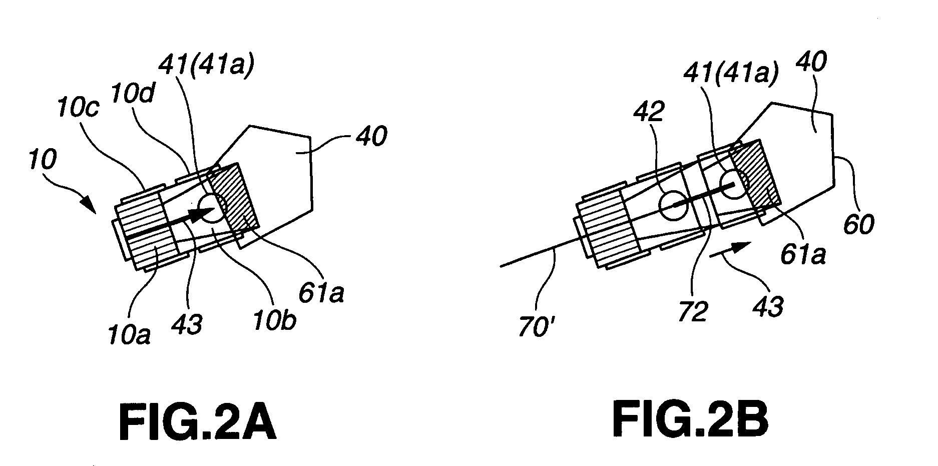
[0134]The first embodiment is applied to the case in which one target earth unloading point 41 (for example, the target earth unloading point 41a) is registered around the hopper pit 40 in the earth unloading site 50. Alternatively, the first embodiment is applied to the case where, even if a plurality of target earth unloading points 41a, 41b, 41c are registered around the hopper pit 40 of the earth unloading site 50, a plurality of unmanned vehicles 10, 10′, 10″ are rarely guided to travel almost within the same interval to the earth unloading points 41a, 41b, 41c of the same hopper pit 40, and to the case where the unmanned vehicle 10 is rarely guided to travel to the hopper pit 40, while other unmanned vehicles 10′, 10″ are being unloaded at the same hopper pit 40. Where other unmanned vehicles 10′, 10′ that were guided earlier are present in the vicinity of the hopper pit 40 when the unmanned vehicle 10 is guided toward the hopper pit 40, this being a rare occasion, the unmanne...

second embodiment

[0161]Similarly to the first embodiment, the second embodiment is also applied to the case in which one target earth unloading point 41 (for example) is registered around the hopper pit 40 within the earth unloading site 50. Alternatively, the second embodiment is applied to the case where, even if a plurality of target earth unloading points 41a, 41b, 41c are registered around the hopper pit 40 of the earth unloading site 50, a plurality of unmanned vehicles 10, 10′, 10″ are rarely guided to travel in almost the same interval to the earth unloading points 41a, 41b, 41c of the same hopper pit 40, and to the case where the unmanned vehicle 10 is rarely guided to travel to the hopper pit 40, while other unmanned vehicles 10′, 10″ are being unloaded at the same hopper pit 40. Where other unmanned vehicles 10′, 10′ that were guided earlier are present in the vicinity of the hopper pit 40 when the unmanned vehicle 10 is guided toward the hopper pit 40, this being a rare occasion, the unm...

third embodiment

[0197]The third embodiment applies to the case in which a plurality of target earth unloading points 41a, 41b, 41c are registered around a hopper pit 40 in an earth unloading site 50. This embodiment also applies to the case in which a plurality of unmanned vehicles 10, 10′, 10″ are guided to travel in almost the same interval to respective earth unloading points 41a, 41b, 41c of the same hopper pit 40, or the case in which the unmanned vehicle 10 is guided to travel to the hopper pit 40, while other unmanned vehicles 10′, 10″ are performing the earth unloading operation at the same hopper pit 40. Thus, this embodiment applies to the case in which interference with other unmanned vehicles 10′, 10″ in the vicinity of the hopper pit 40 has to be taken into account when the unmanned vehicle 10 is directed toward the hopper pit 40.

[0198]The third embodiment will be explained with reference to FIG. 15 and FIGS. 4A, 4B.

[0199]FIG. 4A is a top view of the earth unloading site 50. FIG. 4B sh...


PUM


Abstract

The guided travel control method and guided travel control apparatus capable of creating a traveling course by teaching only target earth unloading points, without traveling through all passage points of the traveling course, prior to the guided traveling, when each traveling course to each target earth unloading point is taught, thereby increasing the efficiency of teaching operation and also increasing the operation efficiency. In the invention, a corrected traveling course for guiding an unmanned vehicle is created based on a hopper detour area, a corrected target earth unloading position, and a target movement direction in a target earth unloading position such that the unmanned vehicle moves in the target movement direction to the corrected target earth unloading position without interfering with the hopper detour area, then the unmanned vehicle is guided to travel along the created corrected traveling course.

Description

BACKGROUND OF THE INVENTION[0001]1. Field of the Invention[0002]The present invention relates to a guided travel control apparatus for an unmanned vehicle, and more particularly to a control method and control apparatus to be applied when an unmanned vehicle such as a dump truck is guided to travel to a hopper pit and an earth unloading operation is performed.[0003]2. Description of the Related Art[0004]At operation sites of large-scale mines, an earth unloading operation is performed in which earth is loaded onto an unmanned vehicle such as a dump truck, transported to a hopper pit, and unloaded into the hopper pit. The unmanned vehicle is guided to travel along a traveling course that was taught in advance.[0005]The operation of earth unloading to a hopper pit is performed, as shown in FIG. 1, by rearing vehicles 10 till the rear wheels thereof touch a wheel stopper at the edge of a hopper pit 40 and setting load-carrying platforms (vessels, bodies) 13b so that they interfere with...

Claims


Application Information

Patent Timeline
IPC IPC(8): G05D1/02G06F19/00
CPCG05D1/0221G05D1/027G05D2201/021G05D1/0278G05D1/0272
Inventor OZAKI, TOMONORI
Owner KOMATSU LTD
Why Eureka
Try Eureka