Eureka AIR delivers breakthrough ideas for toughest innovation challenges, trusted by R&D personnel around the world.

Flat-bed sheet punching machine

Inactive Publication Date: 2008-05-15
HEIDELBERGER DRUCKMASHINEN AG
View PDF7 Cites 0 Cited by
  • Summary
  • Abstract
  • Description
  • Claims
  • Application Information

AI Technical Summary

Benefits of technology

[0009]In order to overcome the problems described above, preferred embodiments of the present invention provide a flat-bed sheet punching layout which can be attended and maintained with minimal expense.
[0011]In a preferred embodiment, two flat-bed sheet punching machines are arranged in the manner of a twin layout opposite to each other in mirror image, so that both machines can be attended and maintained in common by a single attendant. This makes the attendance and maintenance more economical. Furthermore, space is saved, since there needs to be only one attendance space or attendance platform for two punching machines. Thanks to the mirror image layout, it is optimally possible to load the dies from the drive end.
[0012]Furthermore, it is advantageously possible to set up several mirror-image twin layouts alongside each other. In this configuration, the feed units can then load material into the punches arranged alongside each other using common loading logistics and / or the output units can be jointly loaded with empty pallets and / or the output units can be serviced by common logistics.
[0014]In another advantageous preferred embodiment, a joint use of operating data acquisition terminals is possible.

Problems solved by technology

This complex process makes it essential to punch the sheets individually.
The known flat-bed sheet punching machines are relatively cost-intensive in terms of attendance and fitting up.

Method used


Image

  • Flat-bed sheet punching machine
  • Flat-bed sheet punching machine
  • Flat-bed sheet punching machine

Examples


Embodiment Construction

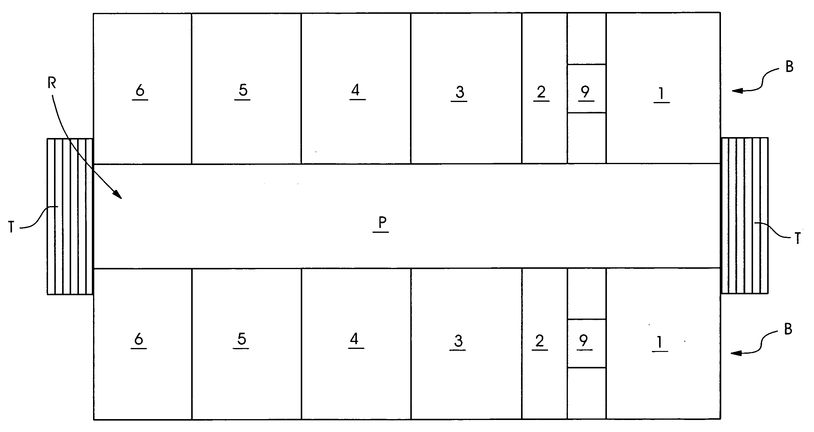
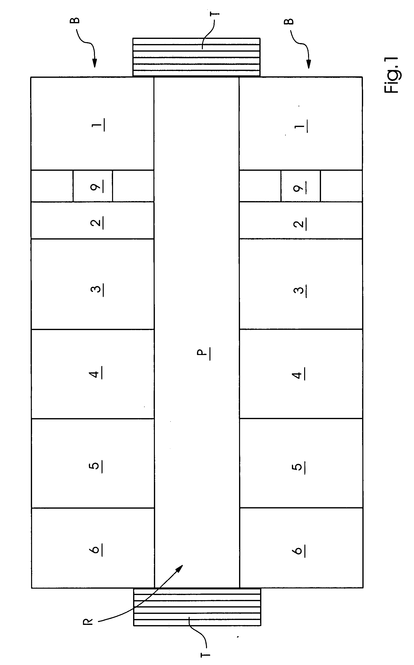
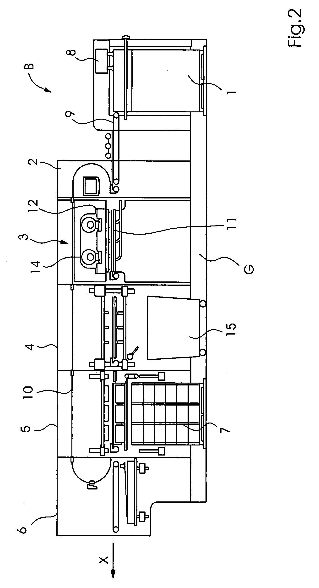
[0018]FIG. 1 shows a flat-bed sheet punching layout preferably including two flat-bed sheet punching machines which serve to process sheet-like materials of paper, cardboard and the like by punching and / or embossing, and in particular, they can be used in the production of paper or cardboard blanks. Each of the flat-bed sheet punching machines B preferably includes, lying one behind the other in the run-through direction X, a feeding and singling mechanism 1, an orienting mechanism 2, a punching mechanism 3, a breaking mechanism 4, a finished copy output mechanism 5 and a separate sheet feed mechanism 6. Furthermore, a pallet station 7 is provided at the finished copy output mechanism 5.

[0019]As is especially evident from FIG. 1, the two flat-bed sheet punching machines B are arranged opposite to each other in mirror image, while in the space R between the two punching machines B there is provided a platform P, by which both punching machines B can be attended at the same time. The ...


PUM


Abstract

A flat-bed sheet punching apparatus includes at least two flat-bed sheet punching machines each having at least one punching mechanism, wherein the at least two flat-bed sheet punching machines are arranged opposite to each other and with an attendant space therebetween such that the at least two flat-bed sheet punching machines can be attended from the attendant space between the at least two flat-bed sheet punching machines.

Description

BACKGROUND OF THE INVENTION[0001]1. Field of the Invention[0002]The present invention concerns a flat-bed sheet punching layout with two flat-bed sheet punching machines, each having at least one punching mechanism.[0003]2. Description of the Related Art[0004]Punching refers to a cutting with closed, geometrical forms, which can be circular, oval, or polygonal, as well as special shapes of every kind. Practices in the post-processing of a print job, such as punching with a hollow punch, rounding corners, and register punching, are also included in this field. The punching is done against a base or against a punch, and sometimes there are also shearing processes (cf. Post-Processing, Training Manual for Bookbinders, Bundesverband Druck e.V. 1996, page 351 et seq.).[0005]Packaging materials of paper, cardboard, paperboard or corrugated cardboard are primarily punched in sheet format. During the punching process, however, crease lines or blind imprints may also be introduced into the f...

Claims


Application Information

Patent Timeline
IPC IPC(8): B26F1/40B26D7/27B26D7/00
CPCB26D7/00B26F1/40B26F1/38Y10T83/4632
Inventor IMKAMP, THOMASPALMEN, PETERSCHMID, FRANK
Owner HEIDELBERGER DRUCKMASHINEN AG
Why Eureka
Eureka Blog
Learn More