Rubber for ships

a technology for ships and rubbers, applied in the direction of hulls, steering components, floating buildings, etc., can solve the problems of rudder blade damage, before the actual rudder blade would be jeopardised, and without costa bulbs,

Inactive Publication Date: 2008-05-15
BECKER MARINE SYST
View PDF1 Cites 8 Cited by
  • Summary
  • Abstract
  • Description
  • Claims
  • Application Information

AI Technical Summary

Problems solved by technology

The Costa bulb however thus protrudes laterally relative to the rudder blade and in the event of the effect of an impact or a blow or pressure it is in the immediate danger zone, before the actual rudder blade would be jeopardised.
But in the event of the effect of an impact or a

Method used


Image

  • Rubber for ships
  • Rubber for ships
  • Rubber for ships

Examples


Embodiment Construction

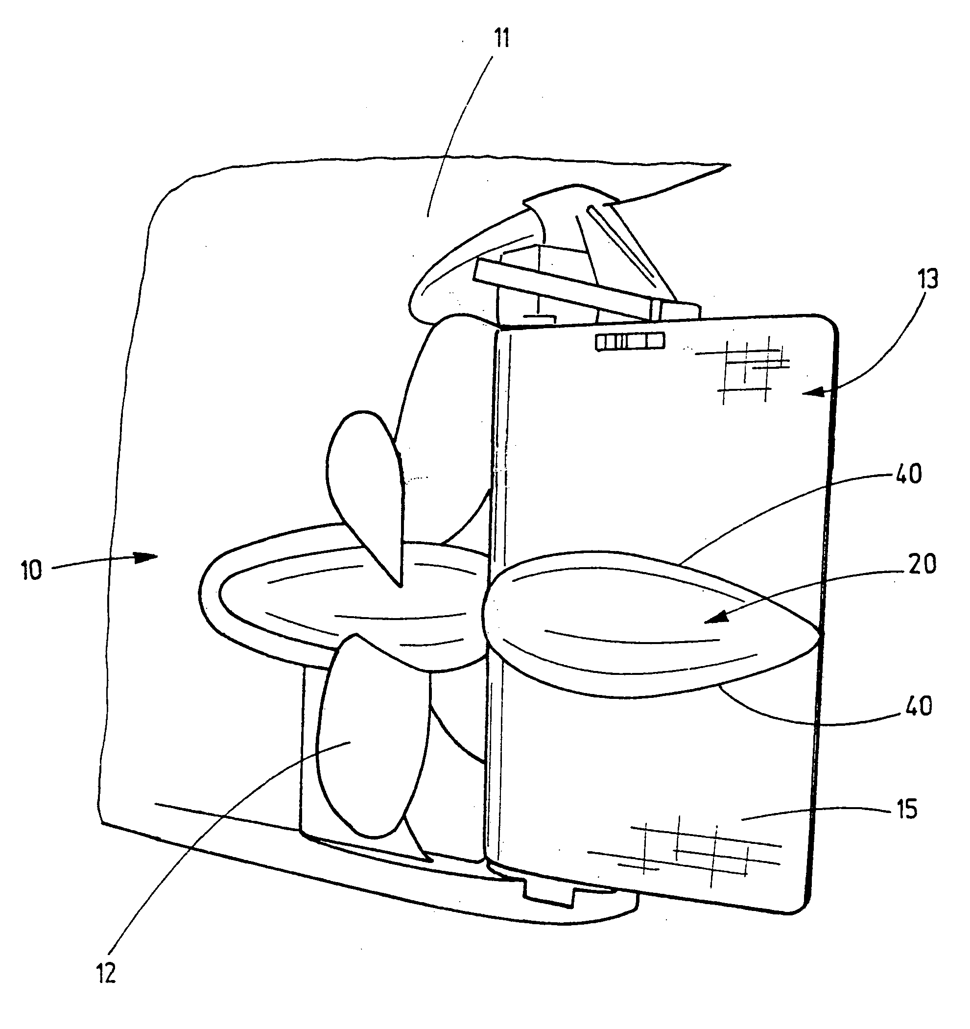
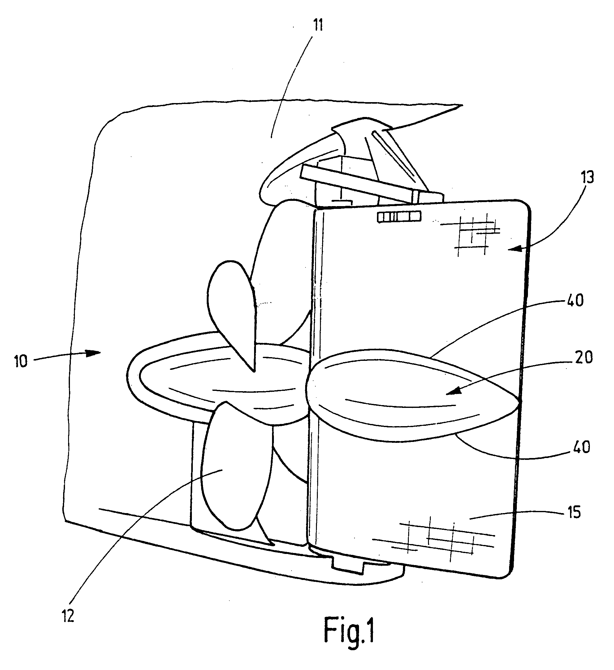
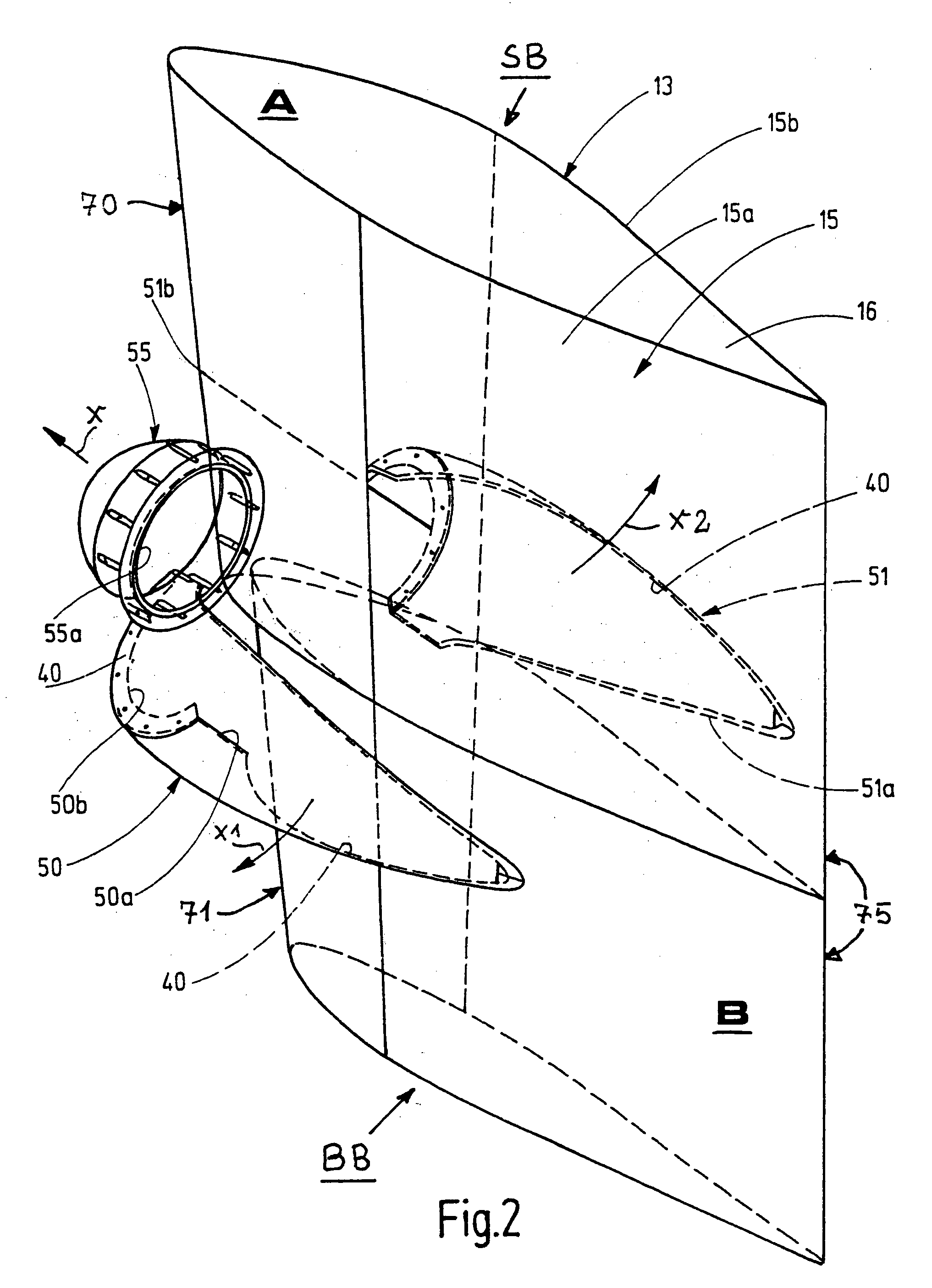
[0030]FIG. 1 shows the stem 11 of a ship 10 with a drive propeller 12 and a rudder 13, whereof the rudder blade 15 is fitted with a bulb-shaped or zeppelin-shaped flow body 20, preferably designed as a hollow body and which can be integrated into the rudder blade 15 and can comprise two or more components 21, 22, attached to the outer wall faces 15a, 15b of the rudder blade 15. The flow body 20 can also be designed as a full body. In extension of the propulsion axis a bulge, which forms the flow body 20, also known as propulsion bulb or Costa bulb, is designed in the region of the rudder blade 1.

[0031]The flow body 20 is designed such that in the event of pressure, blow or impact effect it is self-destroying.

[0032]To achieve the possibility of self-destruction, the wall 25 of the flow body 20 comprises individual wall sections 30, interconnected via predetermined break-off lines 40 in the form of material weaknesses or shear lines (FIG. 6). The predetermined break-off lines are conf...


PUM


Abstract

The invention relates to a rudder for ships with propeller drive, in which the propeller is arranged to rotate about a propulsion axis, with a rudder blade (15) and a flow body (20) arranged on the rudder blade (15), whereby the flow body designed in a bulb or zeppelin shape is arranged as an extension of the propulsion axis in the region of the rudder blade and is designed to self-destruct or self-detach in the event of an increase in the effect of force, blow, impact or pressure.

Description

TECHNICAL FIELD[0001]The invention relates to a rudder for ships in accordance with the preamble of Claim 1.PRIOR ART[0002]Rudders of ships with a propeller drive these days often have a so-called Costa bulb. The purpose of the so-called Costa bulb or propulsion bulb is that a bulge, which is designed bulb-shaped or zeppelin-shaped and constitutes a flow body, is configured as an extension of the propulsion axis in the region of the rudder blade. The purpose of this flow body is that the overall profile of the hub is extended to the point where there is only minimal turbulence of the wake.[0003]This type of Costa bulb is known for example from patents DE 198 44 353 A1, DE 84 23 818 U and DE 82 24 238 U.[0004]The effect of the Costa bulb rests on its bead-shaped configuration, by which it is distinguished from the rudder or respectively rudder blade, resulting in favourable flow.[0005]The Costa bulb however thus protrudes laterally relative to the rudder blade and in the event of the...

Claims


Application Information

Patent Timeline
IPC IPC(8): B63H25/06
CPCB63H25/42B63H1/20B63H25/38B63B3/40
Inventor KLUGE, MATTHIASLEHMANN, DIRK
Owner BECKER MARINE SYST
Why Eureka
Try Eureka