Device and method for optically scanning a machine-readable label applied to an object

a machine-readable label and optical scanning technology, applied in the field of optical scanning machine-readable labels applied to objects, can solve the problems of unfavorable economic development, change in the position of objects on the belt, and unfavorable transportation

Active Publication Date: 2008-05-15
DIEBOLD NIXDORF SYST GMBH
View PDF27 Cites 17 Cited by
  • Summary
  • Abstract
  • Description
  • Claims
  • Application Information

AI Technical Summary

Benefits of technology

[0006]On the other hand, the device in accordance with the invention has the advantage that the objects, independently of their size, can be conducted reliably across the scanning device by an additional transportation device. The transportation device is equipped with several slats or carriers which ensure that the objects are taken individually past the scanning device and are read thereby. There are no special requirements for the size and the shape of the scanning device. The scanning device can be a standard device such as is used in known checkout systems. The apparatus can therefore be produced economically.
[0008]The carriers are matched regarding their shape and their material to the area in which the device operates and the objects, or goods, offered in that area. Since the carriers are advantageously moved at the same speed as the conveyor belt, no force is exerted on the objects by the carriers in the area of the conveyor belt. There is no exertion of force by the carriers on the objects during the conveyance process until the area of the scanning device. The surface of the scanning device with which the objects come into contact as they are being transported is advantageously smooth in order to minimize the friction between the goods and the surface of the scanning device. When selecting the material and the shape of the carriers care must be taken that the resulting strength of the carriers is adequate to withstand the frictional forces and to transport the objects in a reliable manner across the scanning device.
[0010]The carriers cover the scanning device and at least one section of the conveyor belt and the receiving tray which the scanning device is facing. In this way it is ensured that the carriers take the objects first from the conveyor belt to the scanning device, than past the scanning device and finally from the scanning device onto the receiving tray.
[0015]In accordance with a further advantageous embodiment of the invention, the carriers are part of a secondary belt conveyor which has recesses to receive objects. The recesses may be round, oval, rectangular or any type of polygon. The bars or slats which are formed by two successive recesses perpendicular to the conveyor device may be thicker than the sections of the secondary belt conveyor running parallel to the conveyor device. The thickness brings increased stability to the sections running perpendicular to the conveyor device.
[0016]In accordance with a further advantageous embodiment of the invention, the carriers lie directly on the belt conveyor. This ensures that even thin and flat objects are picked up by the carriers and taken across the scanning device.

Problems solved by technology

In this case a relative speed between the carriers and the conveyor belt is avoided which can lead to undesirably high forces affecting the carriers and to a change in position of the objects on the belt because of the friction between the conveyor belt and the objects.

Method used


Image

  • Device and method for optically scanning a machine-readable label applied to an object
  • Device and method for optically scanning a machine-readable label applied to an object
  • Device and method for optically scanning a machine-readable label applied to an object

Examples


Embodiment Construction

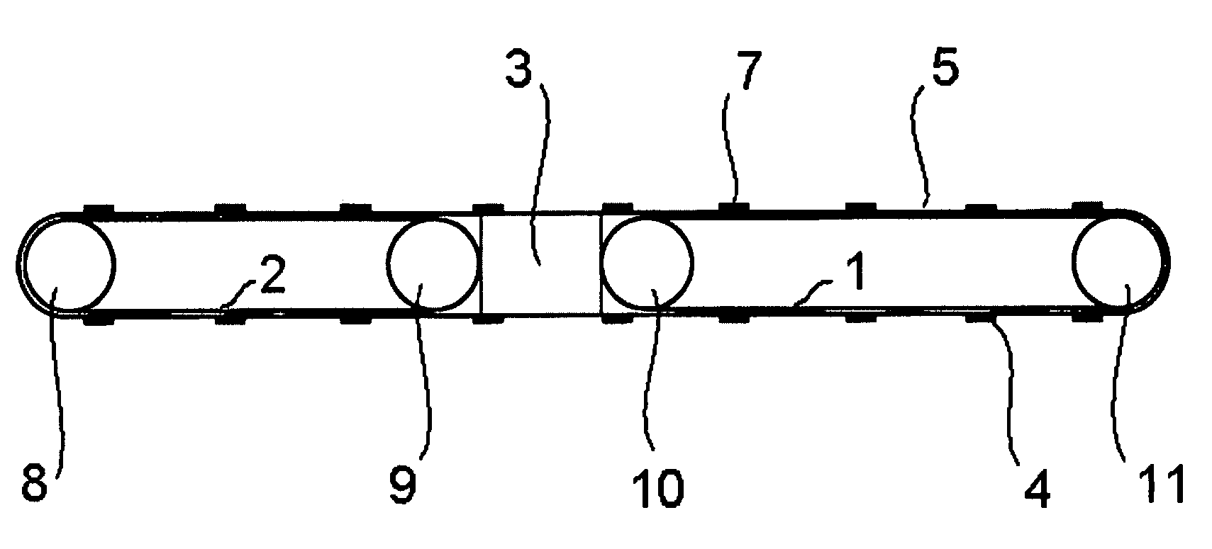
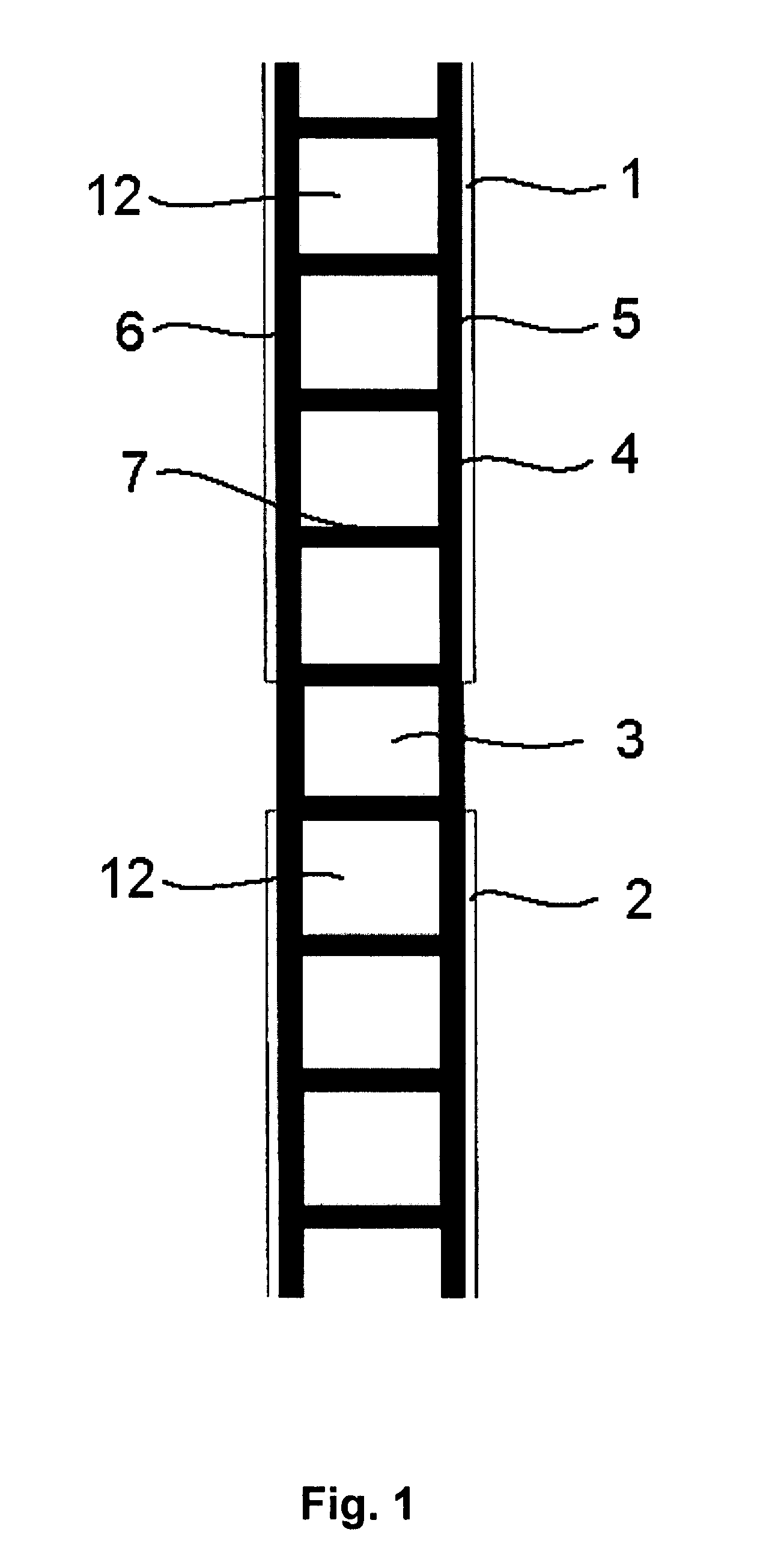
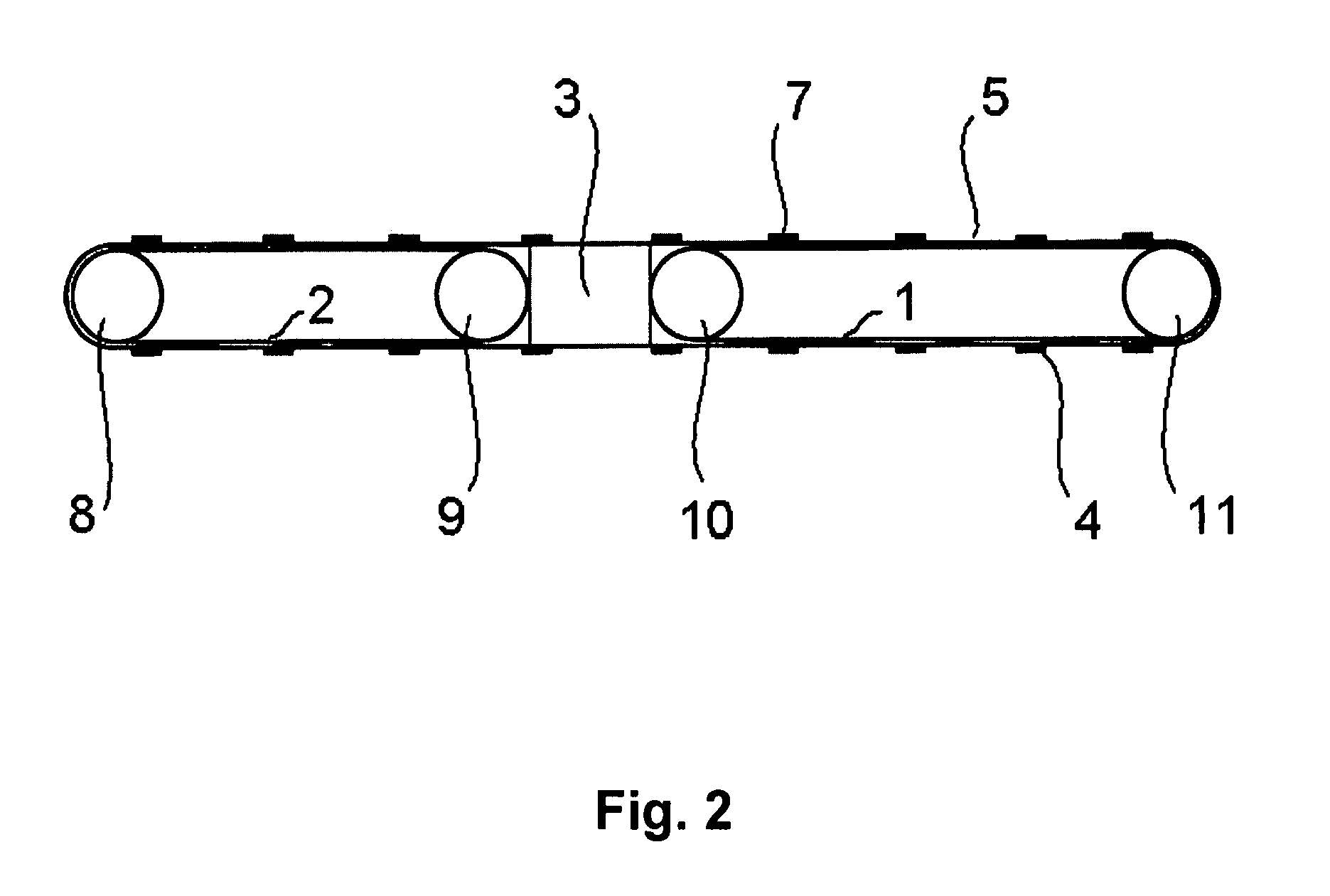
[0021]A device for optically scanning a machine-readable label applied to an object having a first belt conveyor 1, a second belt conveyor 2 and a scanning device 3 is shown in FIGS. 1 and 2. It is also possible to use only belt conveyor 1 and one receiving tray after the scanning device. In the embodiment shown as an example, the scanning device 3 is located between the two belt conveyors 1 and 2. Parallel to the two belt conveyors 1 and 2 runs a supplementary conveyor device 4 which consists essentially of two conveyor belts 5 and 6 and slats 7 located between the conveyor belts. The two conveyor belts 5 and 6 and the slats 7 run directly on the surface of the two belt conveyors 1 and 2 and of the scanning device 3. In order to be able to use as large an area of the belt conveyor 1 as possible when placing objects not shown in the drawing on the belt conveyor 1, the two conveyor belts 5 and 6 run along the sides of the two belt conveyors 1 and 2. The two belt conveyors 1 and 2 are...


PUM


Abstract

A device and a method for the optical scanning of a machine-readable label applied to an object are proposed. The device has at least one belt conveyor (1) and one receiving tray, which are located sequentially spaced apart. A scanning device (3) is located between the belt conveyor (1) and the receiving tray. An additional conveyor device (4) is provided close to the belt conveyor (1) and the scanning device (3) which has several carriers (7) running perpendicular to the direction of travel of the belt conveyor (1). Between two carriers (7) there is a space (12) to accommodate an object. The conveying device (4) covers the scanning device (3) completely and the belt conveyor (1) at least partially. An object is placed on the belt conveyor (1) between two carriers (7) with the side carrying the label and taken across the scanning device (3) by the carriers (7). Then the object is taken to the receiving tray by the carriers (7).

Description

BACKGROUND OF THE INVENTION[0001]1. Technical Field[0002]The invention to a device and a method for optically scanning a machine-readable label applied to an object.[0003]2. Discussion[0004]Such devices and methods are employed, for example, at the check out lanes of a self-service store to read the objects selected by a customer. The objects to be scanned are items. Checking the items out is supposed to take place automatically so that the presence of a check out person is not needed. The label is, for example, a bar code. One or more scanning devices are arranged on a conveyor device in order to read the label on the product. Care must be taken that the items are brought individually to the scanning device and that the label is read by the scanning device when the object with the side showing the label is lying on the belt. The latter is particularly important since most items have labels in only one place and there is a possibility that the customer places the items on the belt w...

Claims


Application Information

Patent Timeline
Patent Type & Authority Applications(United States)
IPC IPC(8): B65G19/02G06K7/10
CPCB65G37/005B65G19/02
Inventor TWISTE, JOSEF
Owner DIEBOLD NIXDORF SYST GMBH
Why Eureka
Try Eureka