Electromagnetic driving apparatus and optical apparatus

a driving apparatus and electromagnetic technology, applied in the field of electromagnetic driving apparatus, can solve the problems of preventing the miniaturization of an interchangeable lens or a camera equipped with the image stabilizing apparatus

Inactive Publication Date: 2008-05-15
CANON KK
View PDF2 Cites 34 Cited by
  • Summary
  • Abstract
  • Description
  • Claims
  • Application Information

AI Technical Summary

Problems solved by technology

This increases the area (volume) of the image-stabilizing apparatus when viewed in the optical axis direction, which impedes the miniaturization of an interchangeable lens or a camera equipped with the image-stabilizing apparatus.

Method used


Image

  • Electromagnetic driving apparatus and optical apparatus
  • Electromagnetic driving apparatus and optical apparatus
  • Electromagnetic driving apparatus and optical apparatus

Examples


embodiment 1

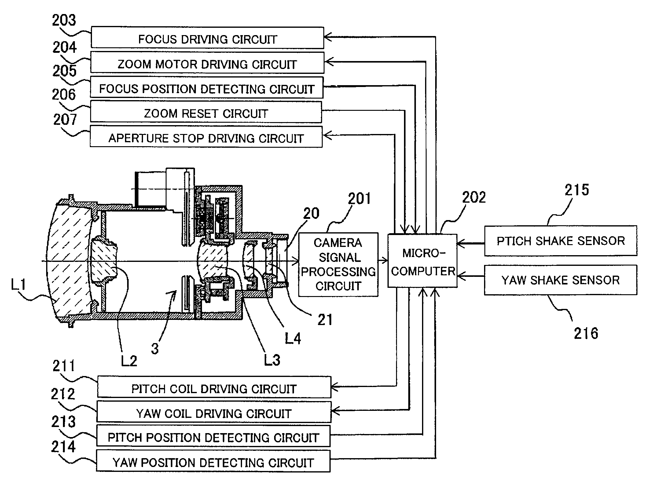
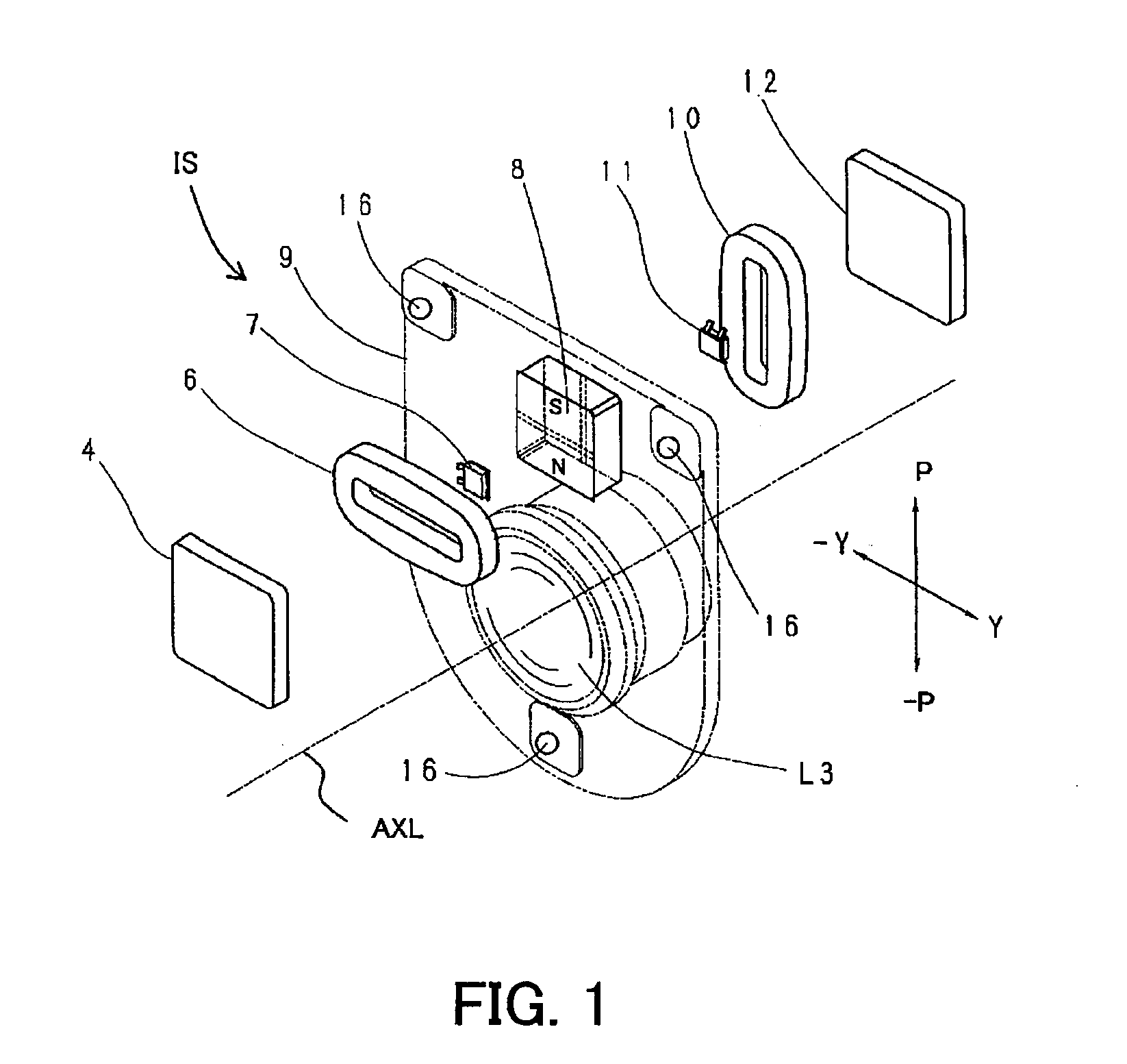
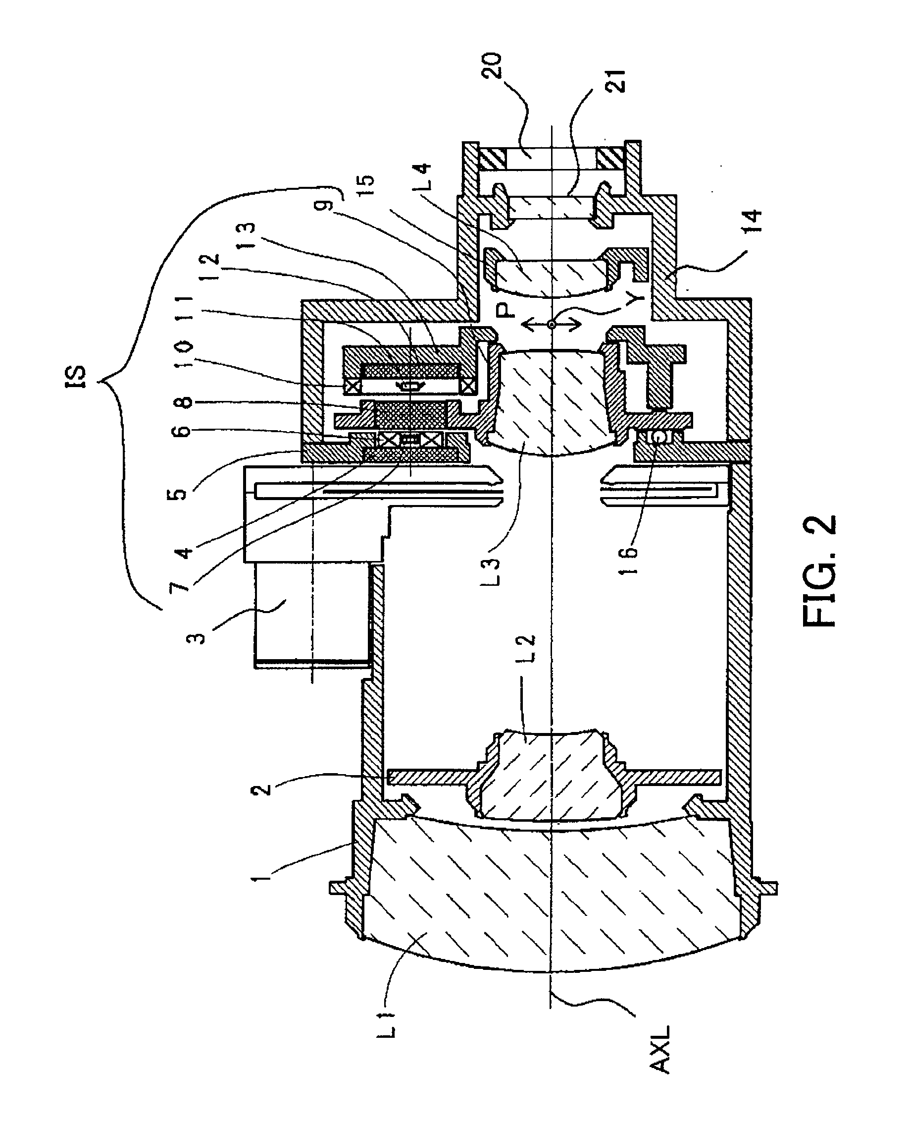
[0018]Description will be first made of the configuration of a video camera as an optical apparatus equipped with an image-stabilizing unit (electromagnetic driving apparatus) that is a first embodiment of the present invention with reference to FIG. 2.

[0019]The image-stabilizing unit (image-stabilizing apparatus) as an embodiment of the present invention can be equipped not only in the video camera but also in various optical apparatuses including an image-pickup apparatus such as a digital still camera and an interchangeable lens. Further, the image-stabilizing unit itself may also be an optical apparatus as an embodiment of the present invention.

[0020]Reference characters L1 to L4 denote first to fourth lens units that are arranged in order from an object side to an image side.

[0021]Reference numeral 1 denotes a fixed barrel holding the first lens unit L1, and 2 a variator-movable frame holding the second lens unit L2 and moving in an optical axis direction to vary the magnificat...

embodiment 2

[0056]The description of the moving-magnet type image-stabilizing unit IS was made in Embodiment 1 in which the driving magnet 8 is moved together with the shift barrel 9. In contrast, description will be made of a so-called moving-coil type image-stabilizing unit in Embodiment 2 in which the driving coil is moved together with the shift barrel.

[0057]FIG. 5 shows part of a video camera equipped with the moving-coil type image-stabilizing unit IS′ that is a second embodiment of the present invention.

[0058]Components identical to those in Embodiment 1 are designated with the same reference numerals and reference characters used in Embodiment 1 and detailed description thereof is omitted. The electrical configuration of the video camera in this embodiment is the same as that shown in FIG. 4.

[0059]Reference numeral 105 denotes a shift base barrel fixed between the fixed barrel 1 and the mount barrel 14. Reference numeral 104 denotes a first driving yoke fixedly held by the shift base ba...

embodiment 3

[0075]FIGS. 6 and 7 show a driving magnet used for an image-stabilizing unit that is a third embodiment of the present invention.

[0076]The driving magnet 308 is constituted by a first magnet plate 301, a second magnet plate 302 and a magnetic plate 303 that is an intermediate member disposed between the first and second magnet plates 301 and 302.

[0077]The front face of the first magnet plate 301 is magnetized such that an S-pole and an N-pole are arranged in the pitch direction P. The rear face of the second magnet plate 302 is magnetized such that an S-pole and an N-pole are arranged in the yaw direction Y.

[0078]The magnetic plate 303 is formed of a magnetic material such as iron. The first and second magnet plates 301 and 302 are respectively absorbed to the front and rear faces of the magnetic plate 303.

[0079]The integration of the first and second magnet plates 301, 302 and the magnetic plate 303 by magnetic adsorption can provide the driving magnet 308 having a function equival...


PUM


Abstract

An electromagnetic driving apparatus includes a magnet member having a first face in which first and second magnetic poles are formed in a first direction and a second face in which the first and second magnetic poles are formed in a second direction, a first coil facing the first face, a second coil facing the second face, a first member holding the magnet member, and a second member holding the first and second coils. One of the first and second members holds a driven member. The first and second members are relatively moved in the first direction by the energization of the first coil, and the first and second members are relatively moved in the second direction by the energization of the second coil. The actuator constituted by the first and second coils and the magnet member can be compactly arranged in one region in the apparatus.

Description

BACKGROUND OF THE INVENTION[0001]The present invention relates to an electromagnetic driving apparatus that drives a driven member and is suitable for, for example, an optical apparatus. The electromagnetic driving apparatus uses electromagnetic force generated between a coil and a magnet to drive an optical element such as a lens or a photoelectric conversion element such as an image-pickup element, for suppressing image shake caused by shake such as hand jiggling.[0002]The optical apparatuses include a so-called image-stabilizing apparatus, an interchangeable lens and an image-pickup apparatus such as a video camera or a digital still camera which are equipped with the image-stabilizing apparatus.[0003]The image-stabilizing apparatus disclosed in such as Japanese Patent Laid-Open No. 11-305277 detects shake such as hand jiggling to drive a lens, depending on the detection result, in a direction different from an optical axis direction (e.g., a direction perpendicular to the optica...

Claims


Application Information

Patent Timeline
Patent Type & Authority Applications(United States)
IPC IPC(8): H04N5/228
CPCG03B5/00
Inventor INABA, HIROYOSHI
Owner CANON KK
Why Eureka
Try Eureka