
Bushing for increased lubrication

a technology of lubrication and lubrication, applied in the direction of sliding contact bearings, bearings, bearing components, etc., can solve the problems of higher friction and faster wear of plain bearings, and achieve the effect of prolonging the lubrication and increasing the life of the bearing

Inactive Publication Date: 2008-05-15
JUSTIN WILLIAM
View PDF11 Cites 46 Cited by
  • Summary
  • Abstract
  • Description
  • Claims
  • Application Information

AI Technical Summary

Benefits of technology

[0012]The present invention relates to bushing used in bearings. The bushing of the present invention are cylindrical and more specifically, two identical semi-cylindrical parts. The inner face of the parts has longitudinal grooves and circumferential grooves, which form a grid-like arrangement. The longitudinal grooves are parallel to the axis of the cylinder and the circumferential grooves are along the inner circumference. The circumferential grooves are preferably broader and deeper than the longitudinal grooves. The part is also provided with at least one through hole on the face. The holes are located at the intersection of the grooves such that, when the lubricant is poured through the holes, it flows into the grooves. The grooves allow the flow of lubricant throughout the inner face, allowing the bushing and shaft assembly to stay lubricated longer and increasing its life.

Problems solved by technology

However, if operating in dry or boundary conditions, plain bearings may wear faster and have higher friction than rolling element bearings.

Method used


Image

  • Bushing for increased lubrication
  • Bushing for increased lubrication
  • Bushing for increased lubrication

Examples


Embodiment Construction

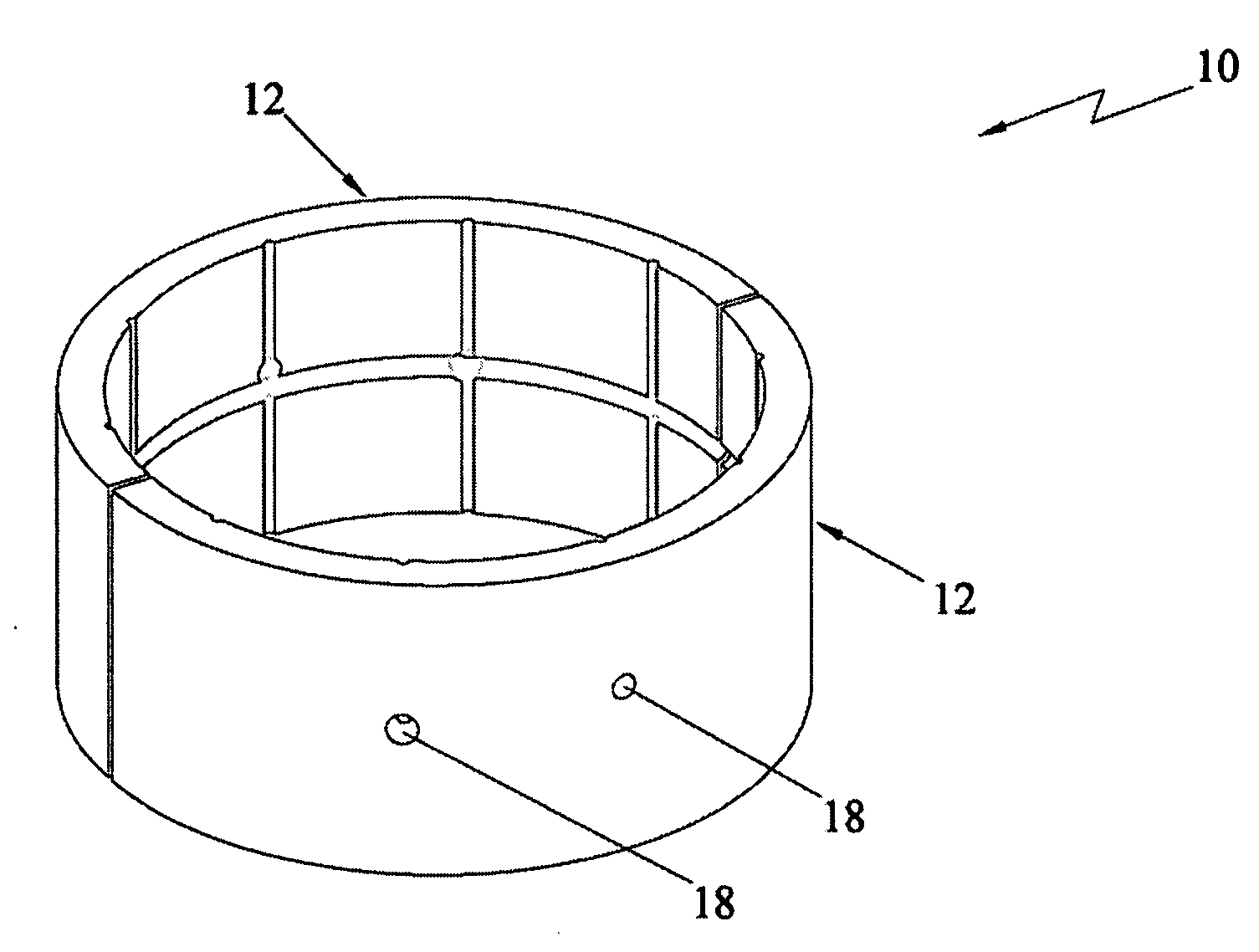
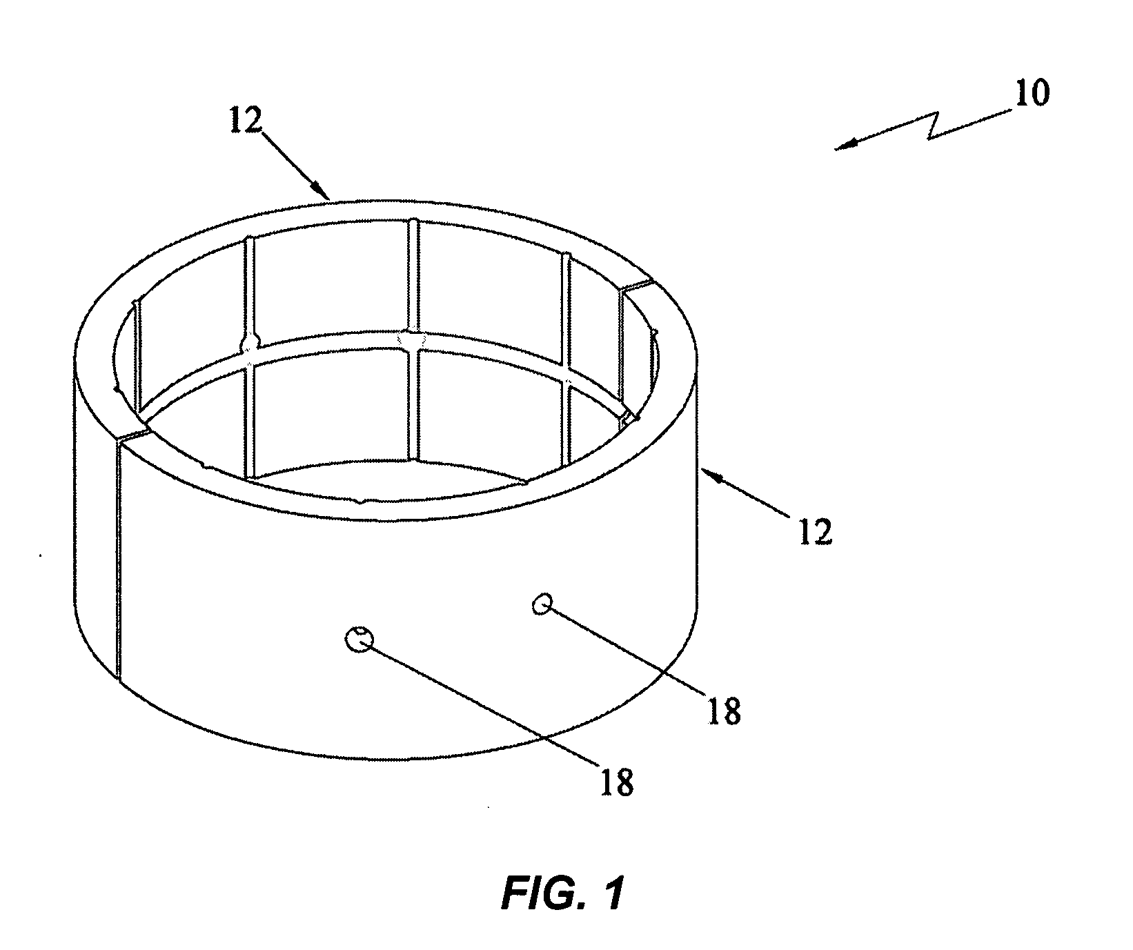
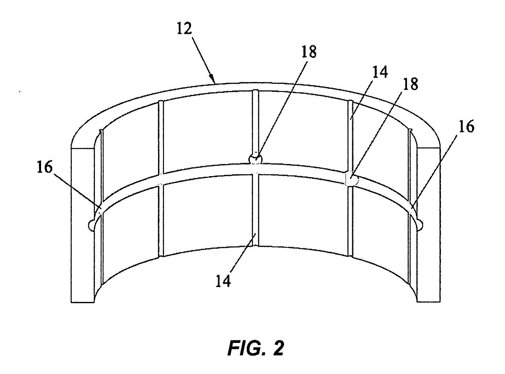
[0015]The novel features of the present invention will become apparent from the following description of a preferred embodiment of the invention and as illustrated in FIGS. 1 through 2. The present invention is a bearing bushing with lubricant dispersion grooves on its inner surfaces for better lubrication.

[0016]Referring to FIGS. 1 through 2, the bushing 10 comprises two identical semi-cylindrical parts 12. The inner face of the parts has longitudinal grooves 14 and circumferential grooves 16, which form a grid-like arrangement. The longitudinal grooves 14 are parallel to the axis of the cylinder and the circumferential grooves 16 are along the inner circumference. The circumferential grooves 16 are preferably broader and deeper than the longitudinal grooves 14. The bushing 10 is also provided with at least one through hole 18 on the face. The holes are located at the intersection of the grooves, 14 and 16, such that when the lubricant is poured through the holes 18, it flows into ...


PUM


Abstract

The present invention relates to bushing used in bearings. The bushing of the present invention is cylindrical with grooves on its inner face, and more particularly grooves which form a grid-like arrangement. Holes are located within the groove such that when lubricant is poured through the holes, it flows into the grooves. The grooves allow the flow of lubricant throughout the inner face, allowing the bushing and shaft assembly to stay lubricated longer and increasing its life.

Description

CROSS-REFERENCE TO RELATED APPPLICATION[0001]This application claim priority to provisional application No. 60 / 859,061 filed on Nov. 15, 2006.FEDERALLY SPONSORED RESEARCH[0002]Not ApplicableSEQUENCE LISTING OR PROGRAM[0003]Not ApplicableBACKGROUND OF THE INVENTION[0004]The present invention relates to bushing, which is a replaceable tube or sleeve, mounted in a case or housing as a bearing. A bushing, more specifically, is a cylindrical lined mechanical device designed to reduce friction and wear, or constrict and restrain the motion of mechanical parts.[0005]A typical bearing is made of two parts. For example a rotary plain bearing can be just a shaft running through a hole. A simple linear bearing can be a pair of flat surfaces designed to allow motion, for example a drawer and the slides it rests on.[0006]Plain bearings may carry load in one of several ways depending on their operating conditions, load, relative surface speed, clearance within the bearing, quality of lubricant an...

Claims


Application Information

Patent Timeline
Patent Type & Authority Applications(United States)
IPC IPC(8): F16C32/06
CPCF16C17/02F16C33/1065F16C33/102
Inventor JUSTIN, WILLIAM
Owner JUSTIN WILLIAM
Features
  • Generate Ideas
  • Intellectual Property
  • Life Sciences
  • Materials
  • Tech Scout
  • Unparalleled Data Quality
  • Higher Quality Content
  • 60% Fewer Hallucinations
Learn More