Optical film, method of manufacturing optical film and liquid crystal display device having the same

a liquid crystal display device and optical film technology, applied in the field of optical film, can solve the problems of more power and not used backlight, and achieve the effects of improving the optical efficiency increasing the brightness of the liquid crystal display device, and reducing the power consumption of the backlight assembly

Inactive Publication Date: 2008-05-15
LG DISPLAY CO LTD
View PDF13 Cites 5 Cited by
  • Summary
  • Abstract
  • Description
  • Claims
  • Application Information

AI Technical Summary

Benefits of technology

[0008]An object of embodiments of the invention is to improve the optical efficiency of a liquid crystal display device, to increase the brightness of the liquid crystal display device, and to reduce the power consumption of a backlight assembly.
[0009]An object of embodiments of the invention provides an optical film having enhanced mechanical strength and thermal durability characteristic, and improved light efficiency.

Problems solved by technology

Therefore, a large portion of light emitted from the light source dose not reach the liquid crystal display panel.
As a result, the overall brightness of the backlight is not used, and more power is required for the backlight unit to provide sufficient brightness to the liquid crystal display device.

Method used


Image

  • Optical film, method of manufacturing optical film and liquid crystal display device having the same
  • Optical film, method of manufacturing optical film and liquid crystal display device having the same
  • Optical film, method of manufacturing optical film and liquid crystal display device having the same

Examples


first embodiment

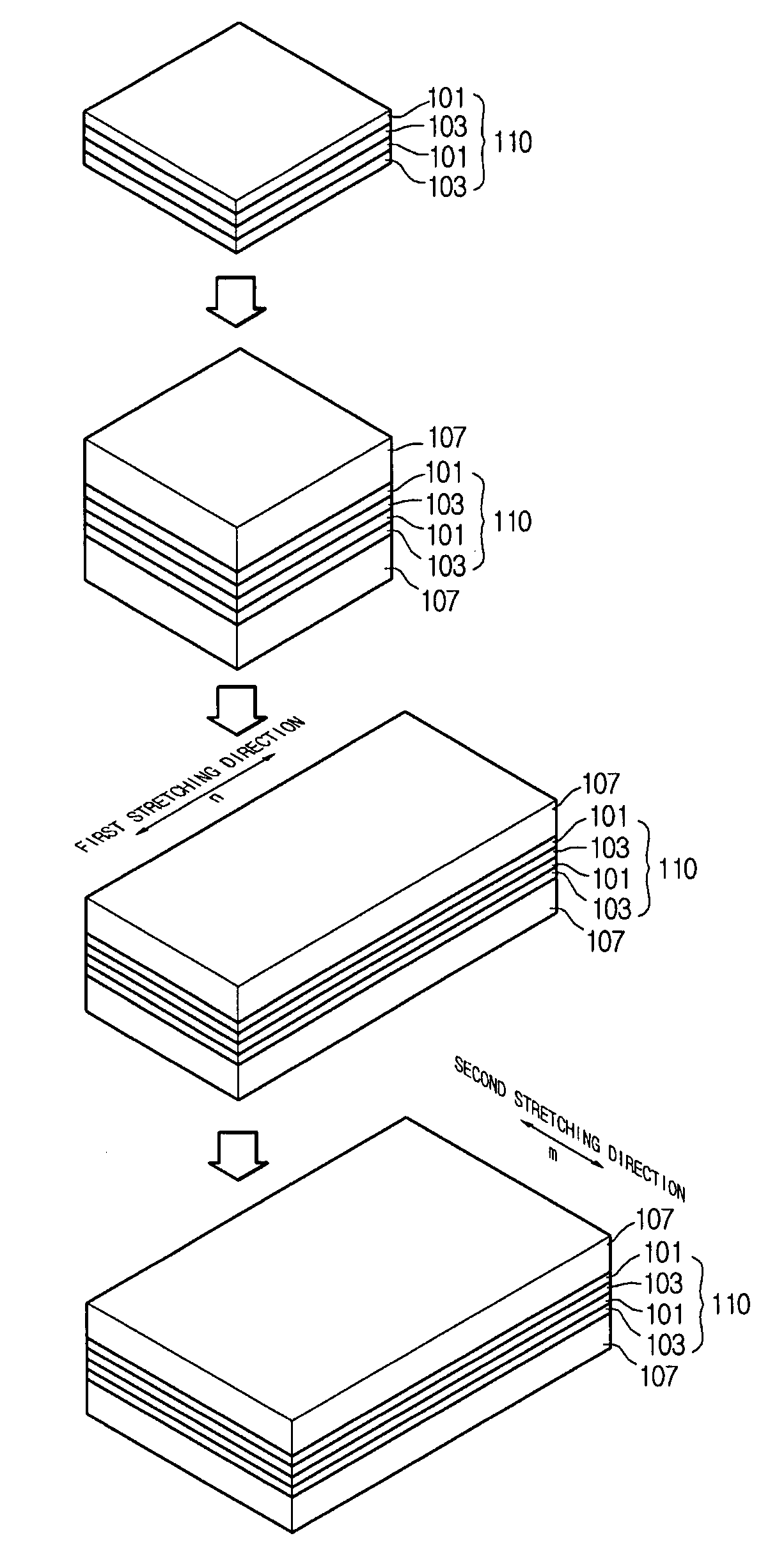
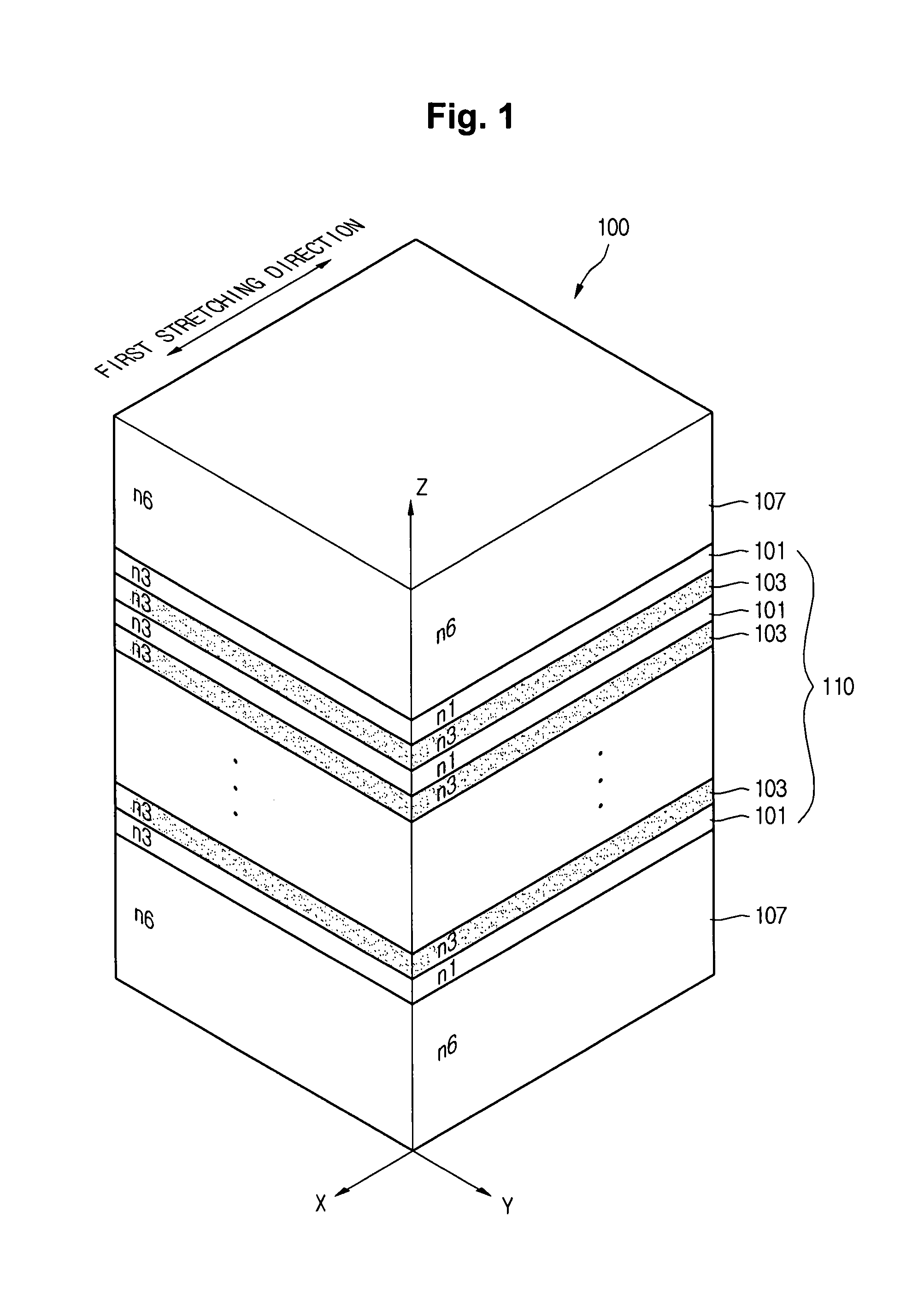
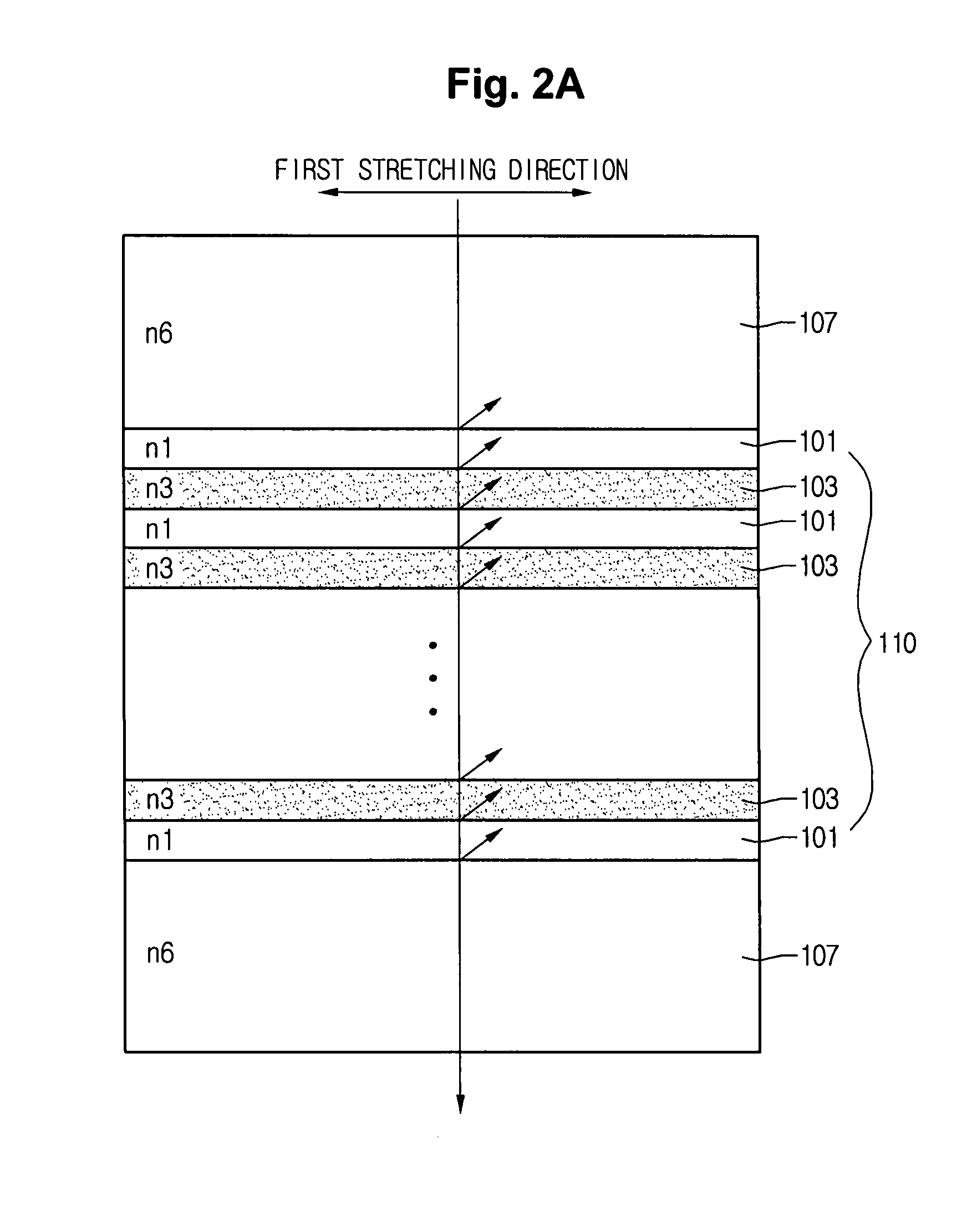
[0034]FIG. 1 shows a perspective view of an optical film according to the invention, FIG. 2A shows a side view of the optical film of FIG. 1 in a stretching direction, and FIG. 2B shows a side view of the optical film of FIG. 1 in a non-stretching direction. Referring to FIG. 1, the optical film 100 includes a multi-layered sheet 110. The multi-layered sheet 110 includes a plurality of polymer layers 101 having a first refractive index n1 in a stretching direction on a plane, and having a third refractive index n3 in a non-stretching direction, and a plurality of copolymer layers 103 alternating with the polymer layers 101, and having the third refractive index n3 in the stretching direction and the non-stretching direction. In an embodiment, the non-stretching direction is perpendicular to the stretching direction on the plane of the optical film 100.

[0035]The optical film 100 further includes a protection sheet 107 directly contacting at least one side of the multi-layered sheet 1...

second embodiment

[0062]FIG. 3 shows a perspective view of an optical film according to the invention. Though the materials, shapes, and numerical values associated with the multi-layered sheet and the protection sheet shown in FIG. 3 are not described in detail, these characteristics are substantially the same as those described in relation to FIG. 1.

[0063]Referring to FIG. 3, the optical film 200 includes the multi-layered sheet 210. The multi-layered sheet 210 includes a plurality of polymer layers 201 having a first refractive index n1 along a first stretching direction on a plane, and having a second refractive index n2 along a second stretching direction, and a plurality of copolymer layers 203 disposed alternately with the polymer layers 201, and having a third refractive index n3 in the first and second stretching directions. The first and second stretching directions can be perpendicular to each other on one plane, or they can have other directions.

[0064]The optical film 200 further includes...

third embodiment

[0099]FIG. 5 shows a perspective view of an optical film according to the invention. Here, since the optical film of FIG. 5 is substantially similar to the optical film of FIG. 1, detailed description of the same or like parts will be omitted. Though the materials, shapes, and the relative position of the multi-layered sheet and the protection sheet shown in FIG. 5 are not described in detail, these characteristics are substantially the same as those described in reference to FIG. 1.

[0100]The optical film 100 includes a first protection sheet 307a and a second protection sheet 307b formed on the upper and lower surfaces of the multi-layered sheet 110, respectively. Each of the first and second protection sheets 307a and 307b can be formed of a copolymer layer and a polymer layer. The first protection sheet 307a serves as an incident plane of light, and can include inorganic particles 309. The inorganic particles 309 include at least one selected from the group consisting of silica, ...


PUM

PropertyMeasurementUnit
weight %aaaaaaaaaa
thicknessaaaaaaaaaa
refractive index n3aaaaaaaaaa

Abstract

An optical film includes a multi-layer sheet having a plurality of polyethylene terephthalate polymer layers, the polymer layers having a first refraction index in a first direction parallel to a plane of the polymer layers and a second refraction index in a second direction parallel to the plane of the polymer layers, and a plurality of polyethylene terephthalate copolymer layers, the copolymer layers having a third refraction index in both the first and second directions, and a protection sheet directly on at least one side of the multi-layer sheet.

Description

[0001]The present application claims the benefits of Korean Patent Application No. 10-2006-0110787 filed in Korea on Nov. 10, 2006, which is hereby incorporated by reference in its entirety.BACKGROUND OF THE INVENTION[0002]1. Field of the Invention[0003]Embodiments of the present invention relate to an optical film, and more particularly to a liquid crystal display (LCD) device having the optical film.[0004]2. Description of the Related Art[0005]Generally, a liquid crystal display device includes a thin film transistor substrate, a color filter substrate, a liquid crystal display panel having a liquid crystal layer interposed between the thin film transistor substrate and the color filter substrate, and backlight unit having a separate light source for supplying light to the liquid crystal display panel. The liquid crystal display device includes a polarizer formed on at least one of the top and bottom surfaces of the liquid crystal display panel. The backlight unit includes the lig...

Claims


Application Information

Patent Timeline
Patent Type & Authority Applications(United States)
IPC IPC(8): C09K19/00B29D7/01B32B7/023
CPCB29C55/023B29K2067/00B32B7/02B32B27/36Y10T428/10G02F1/133606G02F1/13362Y10T428/1091Y10T428/1095G02B5/305G02F2202/28C09K2323/061C09K2323/00B32B7/023
Inventor MOON, JEONG MINJI, BYUNG HWA
Owner LG DISPLAY CO LTD
Why Eureka
Try Eureka