Spinal implant system

a technology of spinal implants and implants, applied in the field of spinal implants, can solve the problems and achieve the effect of substantially non-flexible first forks

Inactive Publication Date: 2008-05-15
WARSAW ORTHOPEDIC INC
View PDF99 Cites 198 Cited by
  • Summary
  • Abstract
  • Description
  • Claims
  • Application Information

AI Technical Summary

Benefits of technology

[0006]The shortcomings of the prior art are overcome and additional advantages are provided in one aspect through an interspinous spacer system which includes a core shaped and configured to fit in an interspinous space between adjacent spinous processes. A plurality of extending forks extends from the core and has shapes configured to extend along the vertical sides of the spinous processes. A first fork of the plurality of forks is moveable relative to the core from a non-use position to an in-use position. The first fork is located on a first side of the core when in the in-use position and has a first inner side bounding an opening for receiving a first spinous process of the spinous processes. The first fork is substantially non-flexible. A second fork is located on the first side of the core and the second fork has a second inner side bounding the opening for receiving the first spinous process of the spinous processes. The second fork is immovable relative to the core. The first fork avoids protruding from the core such that the first fork bounds the opening in the non-use position to allow the core to be inserted into the interspinous space in the non-use position to avoid damage to a supraspinous ligament adjacent the space.
[0007]The present invention provides, in a further aspect, an interspinous spacer system which includes a core having a shape configured to fit between adjacent spinous processes. A plurality of extending forks extends from the core and has shapes configured to extend along vertical sides of the spinous processes. A first fork and second fork of the plurality of forks are coupled to the core and moveable from a non-use position to an in-use position. The first fork and the second fork define an opening for receiving a first spinous process of the spinous processes when in an in-use position. The core includes a cavity defined by inner surfaces of the core and the cavity includes a cavity width between the inner surfaces of the core defining the cavity. A distance between opposite longitudinal outermost surfaces of the first fork and the second fork is less than the cavity width to allow the first fork and the second fork to be received in the cavity in the non-use position to avoid damaging a supraspinous process adjacent the space.
[0009]The present invention provides, in yet a further aspect, a method for spacing adjacent spinous processes which includes providing an interspinous spacer having a non-use position and an in-use position. The spacer includes a core and a plurality of extending forks extending from the core having shapes configured to extend along vertical sides of the spinous processes. The core is inserted, when the spacer is in the non-use position, into a space between the spinous processes from a side of a mid-line of a spine of a patient to avoid damaging a supraspinous ligament adjacent the space. The spacer is moved from the non-use position to the in-use position such that a first fork and a second fork of the plurality of forks coupled to the core define an opening receiving a first spinous process of the spinous processes in the in-use position. The moving includes extending the first fork and the second fork from a cavity of the core with the cavity being defined by inner surfaces of the core. The cavity has a cavity width between the inner surfaces. A distance between opposite longitudinal outer most surfaces of the first fork and the second fork is less than the cavity width to allow the first fork and the second fork to be received in the cavity in the non-use position.

Problems solved by technology

The first fork is substantially non-flexible.

Method used


Image

  • Spinal implant system
  • Spinal implant system
  • Spinal implant system

Examples


Embodiment Construction

[0062]In accordance with the principles of the present invention, spinal implant systems and methods for inserting spinal implants are provided. The implants described herein avoid some or all of the cuts to a supraspinous ligament of a patient by allowing the implants to be inserted from a side of the patient's spine, interspinous space and supraspinous ligament when the implant is configured in a non-use position. The in-situ implant may then be manipulated to an in-use position by a surgeon from the same side as the insertion of the implant without damaging the supraspinous ligament. For example, the implant may be inserted, and manipulated, from a side of a mid-line of a patient's spine when viewed from a posterior thereof.

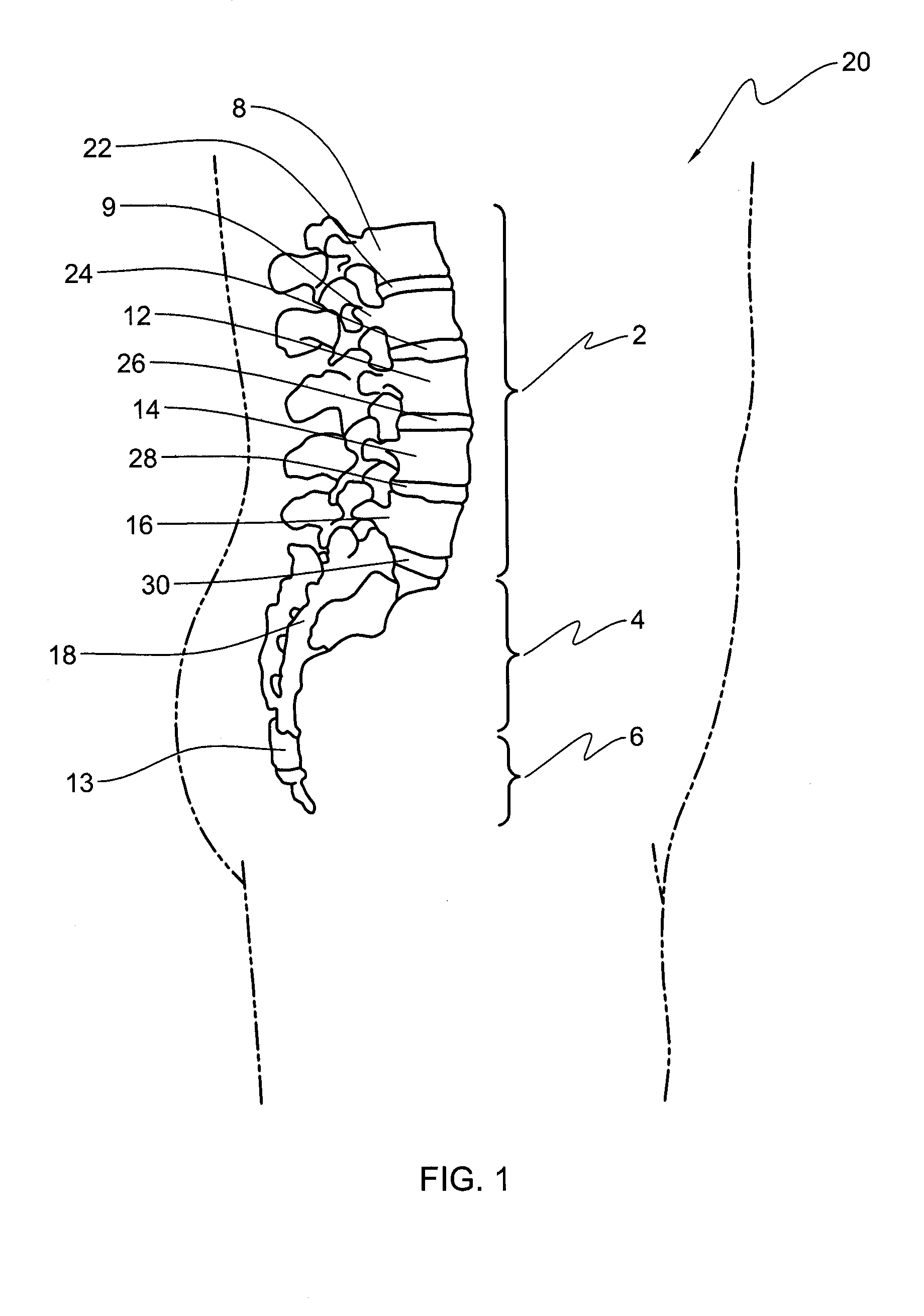
[0063]Referring to FIG. 1, a portion of a spinal column 20 is shown. As depicted, spinal column 20 includes a lumbar region 2, a sacral region 4, and a coccygeal region 6. As is known in the art, column 20 also includes a cervical region and a thoracic region....


PUM


Abstract

An interspinous spacer system includes a core having a shape configured to fit in an interspinous space between adjacent spinous processes. A plurality of extending forks extends from the core and has shaped configured to extend along vertical sides of the spinous processes. A first fork of the plurality of forks is moveable relative to the core from a non-use position to an in-use position. The first fork is located on a first side of the core in the in-use position and has a first inner side defining an opening for receiving a first spinous process of the spinous processes. The first fork is substantially non-flexible. A second fork is located on the first side of the core and has a second inner side defining an opening for receiving the first spinous process of the spinous processes. The second fork is immovable relative to the core. The first fork avoids protruding from the core such that the first fork bounds the opening in the non-use position to allow the core to be inserted into the interspinous space.

Description

TECHNICAL FIELD[0001]The present invention relates generally to the field of surgery and medical implants, and more particularly, to spinal implant systems and methods for inserting spinal implant systems.BACKGROUND OF THE INVENTION[0002]The human spine is a biomechanical structure with thirty-three vertebral members, and is responsible for protecting the spinal cord, nerve roots and internal organs of the thorax and abdomen. The spine also provides structural support for the body while permitting flexibility of motion. A significant portion of the population will experience back pain at some point in their lives resulting from a spinal condition. The pain may range from general discomfort to disabling pain that immobilizes the individual. Back pain may result from a trauma to the spine, be caused by the natural aging process, or may be the result of a degenerative disease or condition.[0003]Procedures to remedy back problems sometimes require correcting the distance between vertebr...

Claims


Application Information

Patent Timeline
Patent Type & Authority Applications(United States)
IPC IPC(8): A61F2/44
CPCA61B17/842A61B17/7065A61B17/7053
Inventor DEWEY, JONATHAN M.LYONS, LAURENPATTERSON, CHRISTOPHER M.
Owner WARSAW ORTHOPEDIC INC
Why Eureka
Try Eureka