[0004]Therefore, a purpose of the present invention is to provide a robot hand able to change the manner of holding the object while force applied from the plurality of finger mechanisms to the object is adjusted without using the auxiliary finger mechanism, and a robot having the robot hand.
[0006]In accordance with the robot hand of the first invention, when the force applied to the object from the certain finger mechanism among the plurality of finger mechanisms is changed, the operation of each finger mechanism is controlled such that the “contact” of each finger mechanism in the object and the “application
force vector” from each finger mechanism to the object satisfy the “stable gripping condition”. The “stable gripping condition” is a condition in which (1) the sum of each of forces and moments applied from the plurality of finger mechanisms to the object becomes zero and (2) the slip index becomes minimum. The “slip index” is defined as a decreasing function of the magnitude of an inner product of a vector perpendicular to the axis of a frictional cone of the object with respect to each finger mechanism, and an application
force vector from each finger mechanism to the object. Since the condition that the forces and moments applied from the plurality of finger mechanisms to the object become zero is satisfied, the situation of greatly changing the position and posture of the object with respect to the robot hand is avoided. Further, the situation of slipping the finger mechanisms with respect to the object is avoided or restrained by satisfying the condition of minimizing the slip index.
[0007]Accordingly, in a process in which force applied to the object from a certain finger mechanism among the plurality of finger mechanisms is gradually weakened and becomes zero and the certain finger mechanism is separated from the object, a balance of the forces applied from the plurality of finger mechanisms to the object can be appropriately adjusted from the view point of object gripping. Further, in a process in which the finger mechanism separated from the object is again abutted on the object and the force applied from this finger mechanism to the object is gradually strengthened, the balance of the forces applied from the plurality of finger mechanisms to the object can be appropriately adjusted from the view point of the object gripping. The changing of the manner of holding the object involving the above separation of the certain finger mechanism from the object and the reabutting onto the object can be smoothly executed.
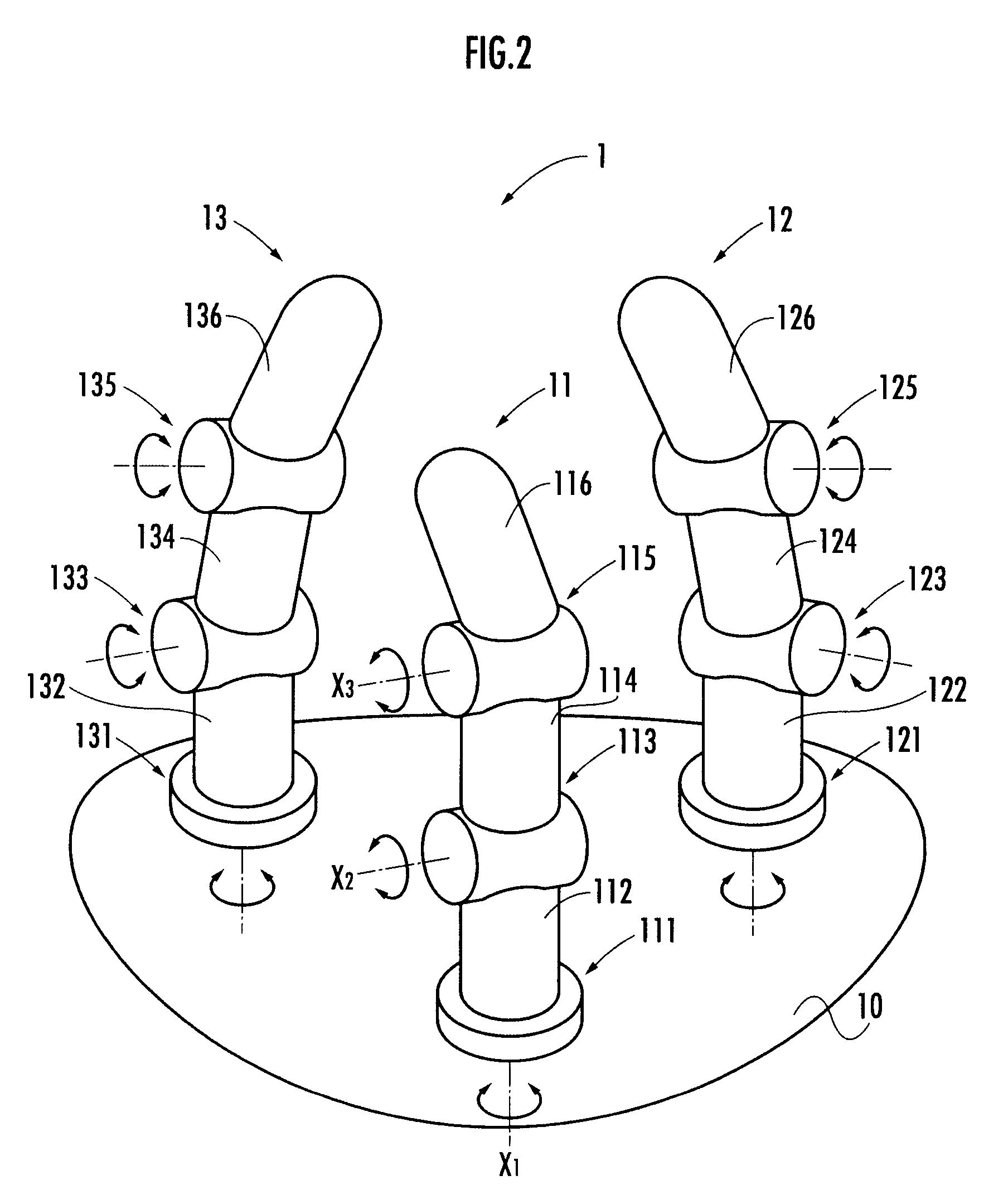
[0009]In accordance with the robot hand of the second invention, when the force applied from the
third finger mechanism to the object is changed in a state in which the object is gripped by three finger mechanisms, i.e., the first finger mechanism and the second and
third finger mechanisms opposed to the first finger mechanism, the magnitude and direction of the force applied to the object from the first and
second finger mechanisms are adjusted in consideration of the slip index reflecting arrangements of the first, second and third contacts and the like. Thus, the changing of the manner of holding the object involving the separation of the
third finger mechanism among the three finger mechanisms from the object and the reabutting onto the object can be smoothly executed.
[0011]In accordance with the robot hand of the third invention, force applied to the object from at least a certain finger mechanism among the finger mechanisms continuously abutting on the object in changing the manner of holding the object is adjusted to its upper
limit value. Thus, frictional force of this finger mechanism and the object is strengthened and it can be prevented or restrained that the finger mechanism is slipped with respect to the object.
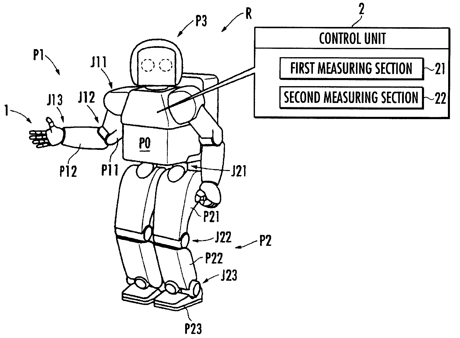
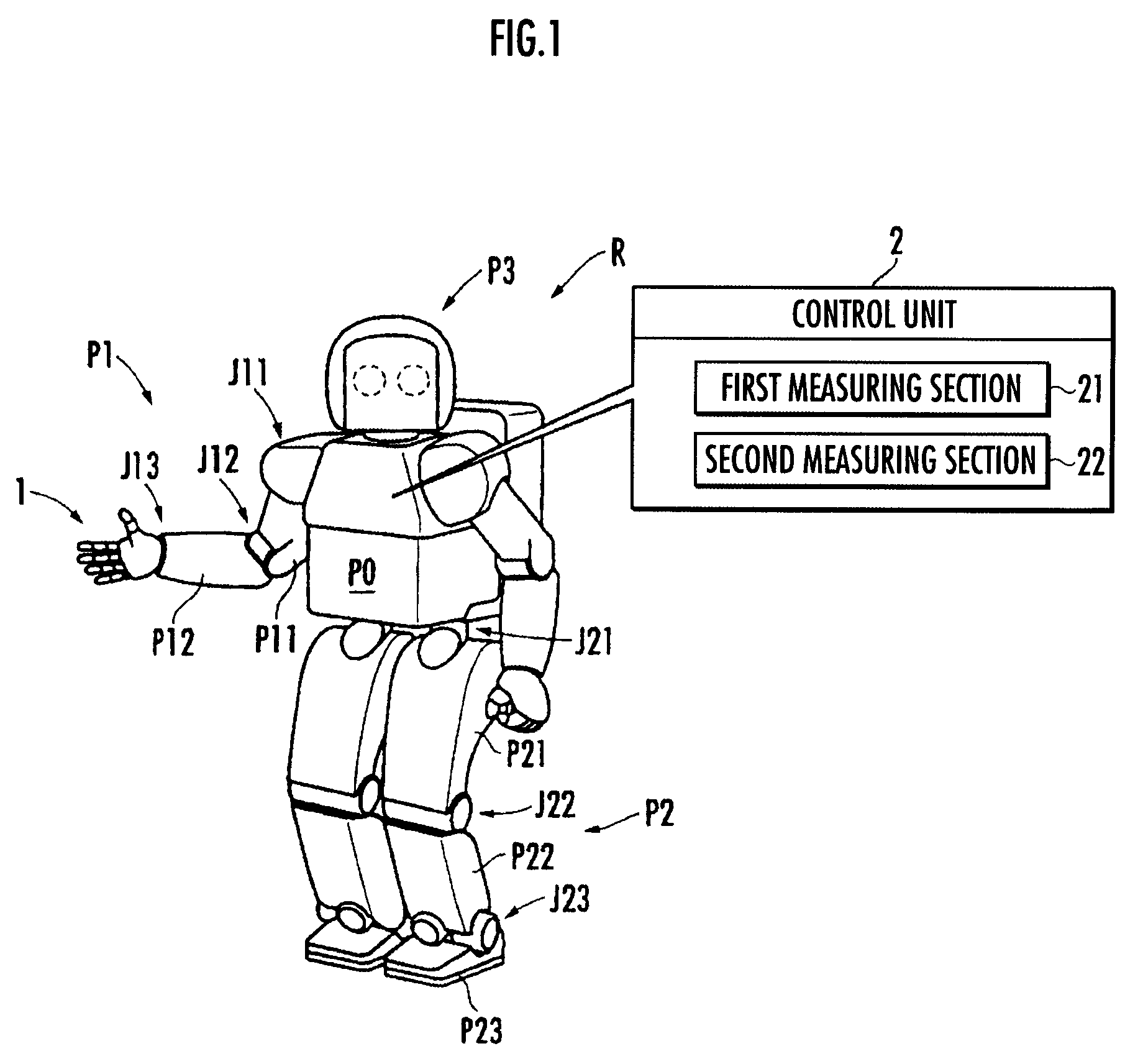
[0013]In accordance with the robot of the fourth invention, when force applied to the object from the certain finger mechanism among the plurality of finger mechanisms is changed, the operation of each finger mechanism is controlled such that the “contact” of each finger mechanism in the object and the “application force vector” from each finger mechanism to the object satisfy the “stable gripping condition”. Thus, a slip of the finger mechanism with respect to the object and unbalance of the posture of the object with respect to the robot hand are prevented. Further, the changing of the manner of holding the object involving the separation of the certain finger mechanism from the object and the reabutting onto the object can be smoothly executed.

