System and method of dynamic power management

a dynamic power management and power management technology, applied in the field of dynamic power management system and method, can solve the problems of increasing the physical bulk of cabling, requiring more space, and long-standing disadvantages of this approach, so as to maximize the power available, minimize the total number of network devices, and minimize the power allocated to each individual network device.

Active Publication Date: 2008-05-15
AVAGO TECH INT SALES PTE LTD
View PDF9 Cites 90 Cited by
  • Summary
  • Abstract
  • Description
  • Claims
  • Application Information

AI Technical Summary

Benefits of technology

[0025]The method of the present invention thus provides dynamic power management, wherein the power allocated to each individual network device may be minimized, and wherein as a result the total number of network devices that can be supported with the available power may be maximized. One result may be a more efficient utilization of the available power.

Problems solved by technology

The disadvantages of this approach have long been obvious.
Using two cables increases the physical bulk of cabling which must be wired through the physical environment, demanding more space and making it more difficult to track which cables are serving which functions.
Some PRDs have required transformers co-located with the PRD, further increasing bulk and complicating deployment efforts.
Overall, dual cable solutions typically cost more than a single cable solution and tend to be unwieldy to deploy and maintain.
In addition, a key limitation of dual cable solutions is that they inherently tend to exclude the transmission of data which is related to the power consumption of a PRD.
For example, if a PRD is plugged directly into a wall socket, or connected to a wall socket via a dedicated UPS or transformer, there typically does not exist any means to monitor the power delivered to the PRD, nor to regulate the power delivered to the PRD.
In turn, this makes it difficult to monitor and control overall network power consumption.
A problem has existed, however, in adapting certain widely used legacy technologies to take advantage of single cable power and data solutions.
In particular, Ethernet communications systems, which are widely deployed for wired computer networks worldwide, have long relied on one cable (the Ethernet cable) to carry data to PRDs and another separate cable to supply power to the PRDs, with all the disadvantages already noted above.
One problem is that, in real-world operation, PRDs often use significantly less power than the maximum power they might request.
However, in actual use, the PRD might never use anywhere near this much power, or possibly the PRD might draw near the maximum power at infrequent intervals, while using dramatically less power most of the time.
If many devices are connected to the DCE, a further result may be that insufficient power is available to power all the devices, leaving some devices effectively non-operational.
A further short-coming of existing power technologies is that they provide no way to prioritize attached network devices.
A further shortcoming of present technologies is that, in the event of a sudden decrease in available power, no method is provided to deallocate power from the PRDs.

Method used


Image

  • System and method of dynamic power management
  • System and method of dynamic power management
  • System and method of dynamic power management

Examples


Embodiment Construction

I. Introduction

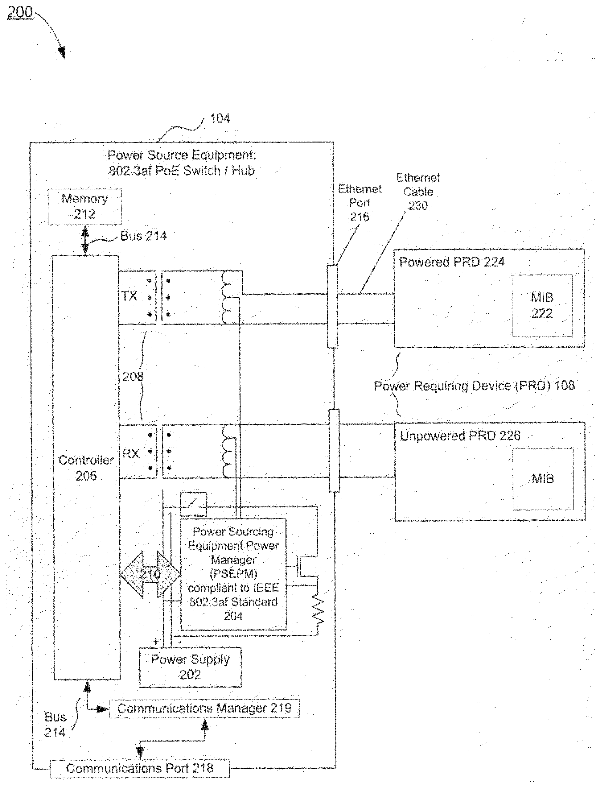
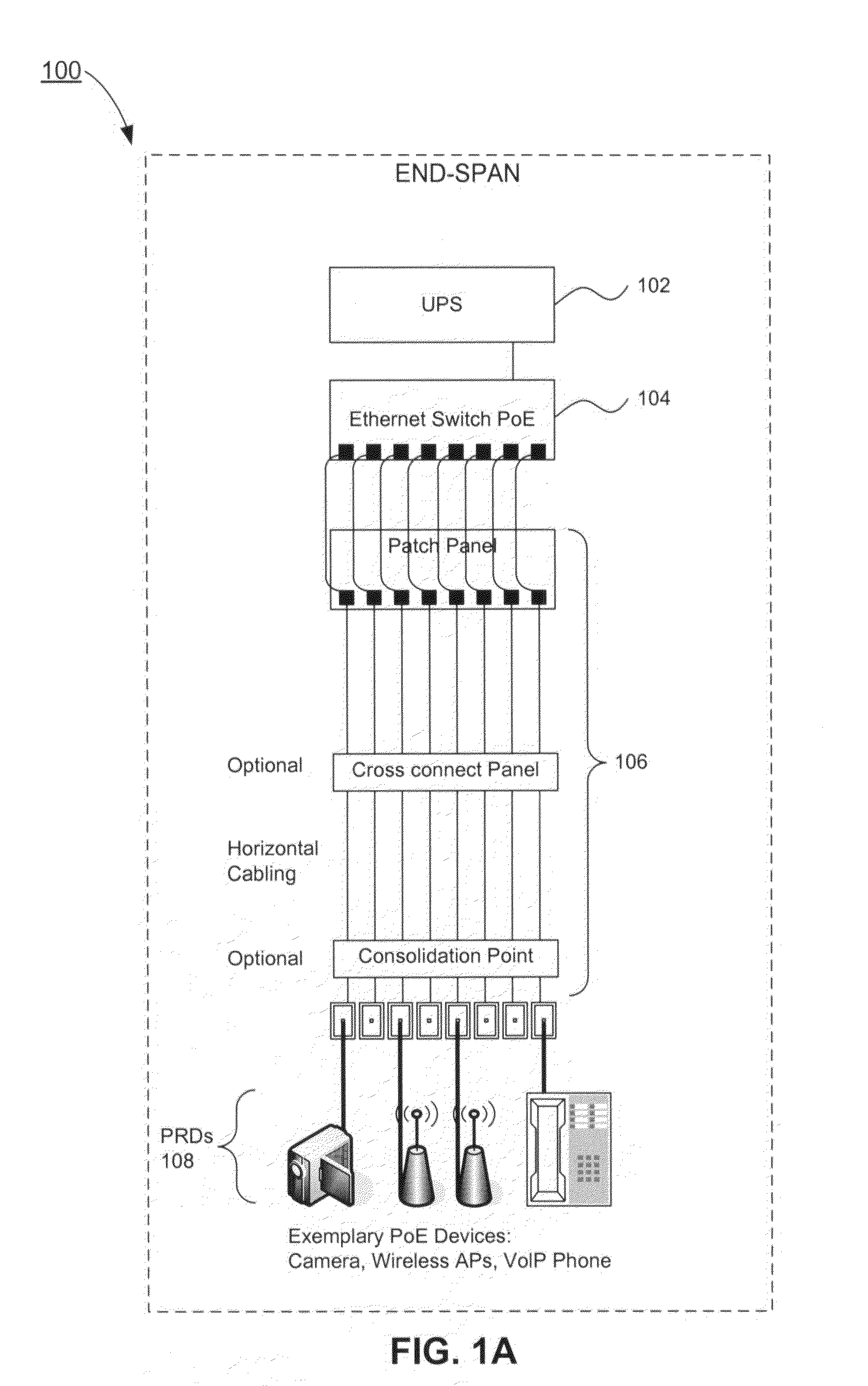
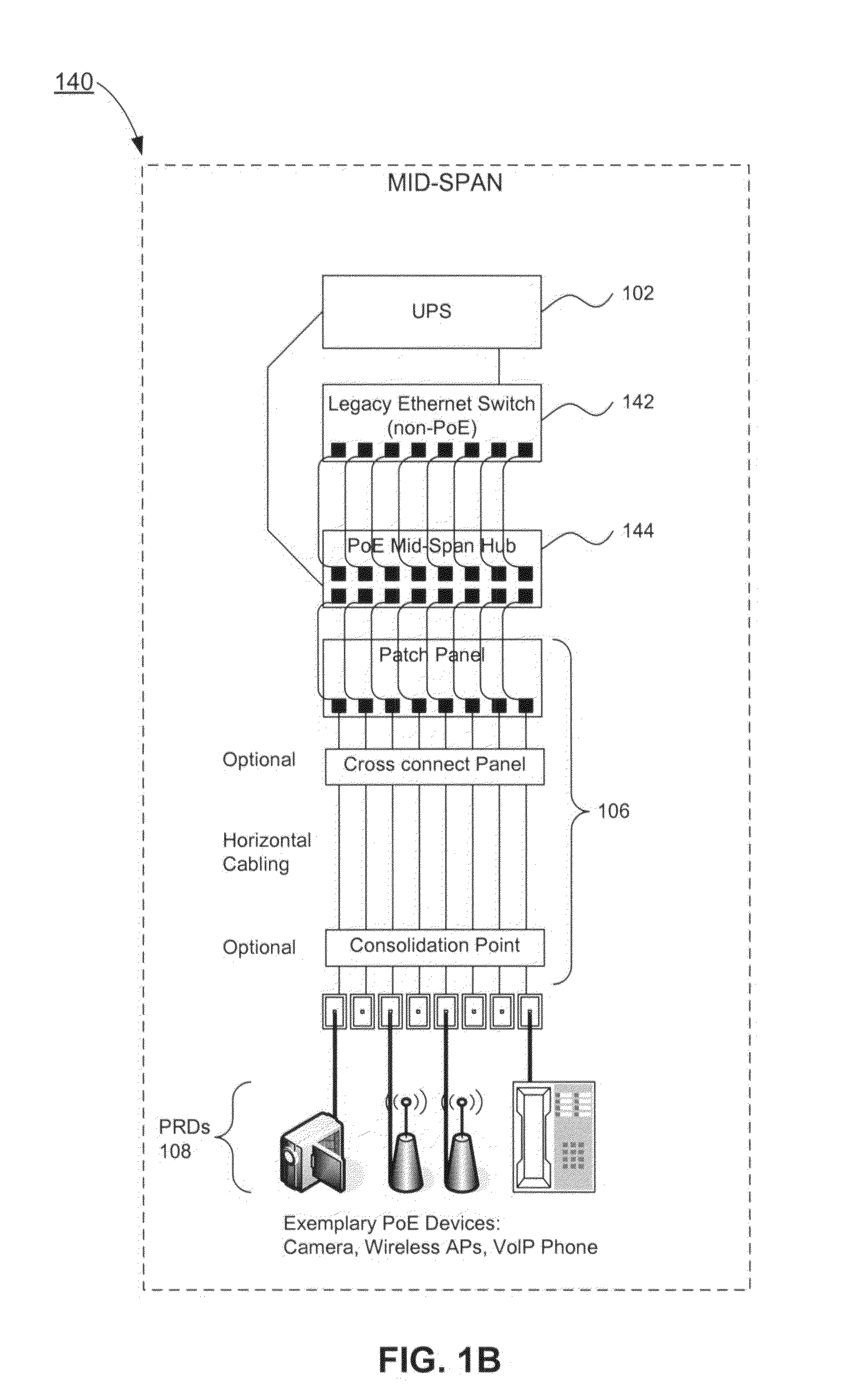
[0038]The present invention is directed to a system and method for dynamic power management and allocation in a communications system or communications network. In an exemplary embodiment, power is provided from power source equipment (PSE) to one or more power requiring devices (PRDs) via a means of power conveyance, such as network cabling. In one embodiment of the present invention, the PSE is contained in the same hardware unit or device which also serves as the data communications equipment (DCE), that is, the hardware unit or device which transmits data to and / or accepts data from the PRDs. Further, data sent back and forth via the means of power conveyance may include, in addition to any network communications proper, data which is related to power management of the PRD or PRDS.

[0039]It should be understood that this communications system configuration is exemplary only, and other communications system or network configurations are possible and are consistent w...


PUM


Abstract

In a communications system, such as a Power-Over-Ethernet system, where power supply equipment (PSE) supplies power to powered requiring devices (PRDs), a system and method of dynamic power management is implemented. The system and method monitors the power consumed at each port by the PRDs. Based on this monitoring, the PSE dynamically determines the minimum power which can be allocated to each PRD, and so dynamically maximizes the available reserve power. The PSE maintains a queue or queues wherein PRDs are listed in order of a power allocation priority. When additional power is available, the PSE preferentially allocates power to a PRD or PRDs which have higher priority. The system and method of the present invention minimizes the power allocated to each individual network device, as a result of which the total number of network devices that can be supported with the available power may be maximized.

Description

CROSS REFERENCE TO RELATED APPLICATIONS[0001]This patent application claims the benefit of U.S. Provisional Patent Application No. 60 / 858,937, filed Nov. 15, 2006, entitled “System And Method Of Dynamic Power Management,” which is incorporated herein by reference in its entirety.BACKGROUND OF THE INVENTION[0002]1. Field of the Invention[0003]The present invention pertains to the field of providing power from power source equipment (PSE) to one or more devices which are part of a communications system or communications network, and to managing the power which is supplied to the networked devices.[0004]2. Background Art[0005]Network devices which require power are conventionally referred to in the art as “powered devices”, or “PDs” for short. In this document, for reasons explained further below, such devices will be referred to as “power requiring devices”, or “PRDs”, wherein the terms “power requiring device”, “PRD”, and the plurals thereof are entirely synonymous with the terms “po...

Claims


Application Information

Patent Timeline
Patent Type & Authority Applications(United States)
IPC IPC(8): G06F1/28
CPCH04L12/10
Inventor CHIN, DAVID KUN
Owner AVAGO TECH INT SALES PTE LTD
Why Eureka
Try Eureka