
Bar Connecting Apparatus

a technology of connecting apparatus and bar, which is applied in the direction of metal working apparatus, manufacturing tools, building components, etc., can solve the problems of bending required and not addressing the time and labor needed to connect the rebar

Active Publication Date: 2008-05-22
DAYTON SUPERIOR CORP
View PDF72 Cites 30 Cited by
  • Summary
  • Abstract
  • Description
  • Claims
  • Application Information

AI Technical Summary

Benefits of technology

[0011]The clip feed assembly utilizes at least one finger to engage and advance the clip string into the clip receiving cavity. The finger has a pivot point and a sloped side so the finger can ratchet backwards along the clip string before engaging and urging the clip string forward into the clip receiving cavity. The backwards ratcheting motion and forward engaging motion allows the finger to advance clips into the clip receiving cavity as the clip feed assembly reciprocates laterally with each cycle of the hammer.

Problems solved by technology

This is labor intensive, slow, and tends to cause injuries from the repeated bending.
This can reduce the bending required, but does not address the time and labor needed to connect the rebar.

Method used


Image

  • Bar Connecting Apparatus
  • Bar Connecting Apparatus
  • Bar Connecting Apparatus

Examples


Embodiment Construction

Clip String

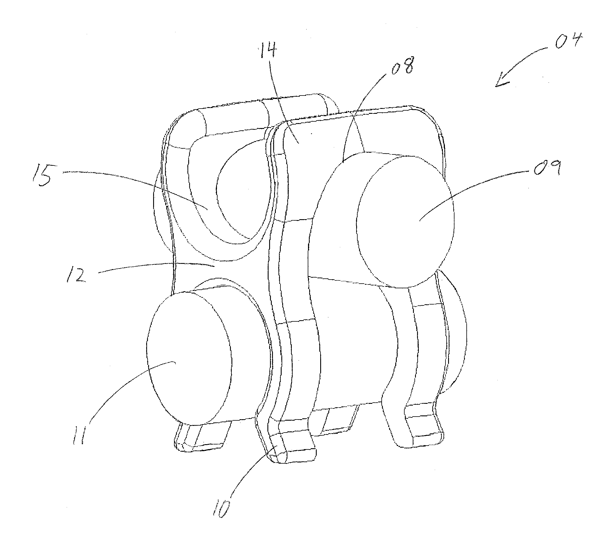
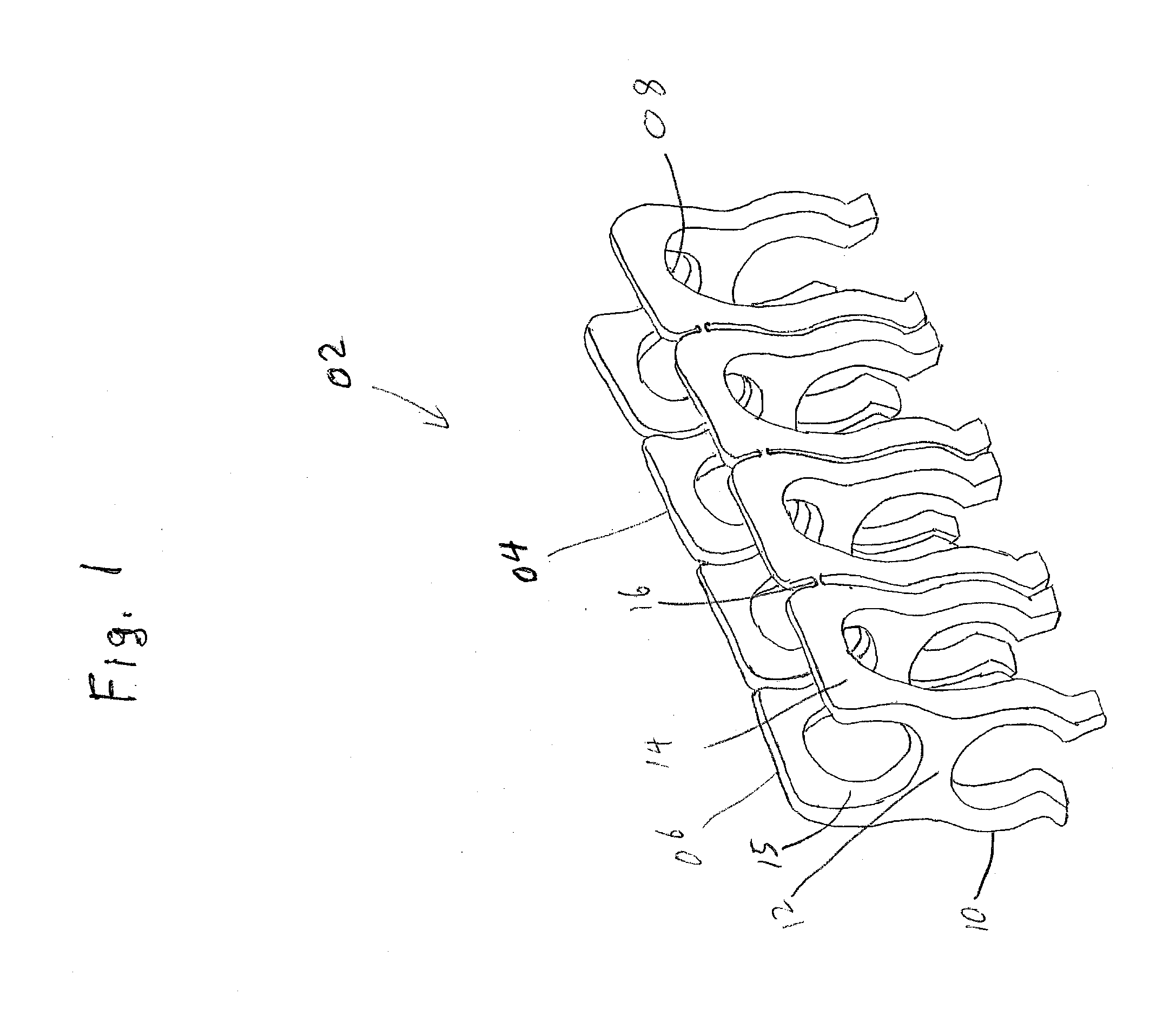
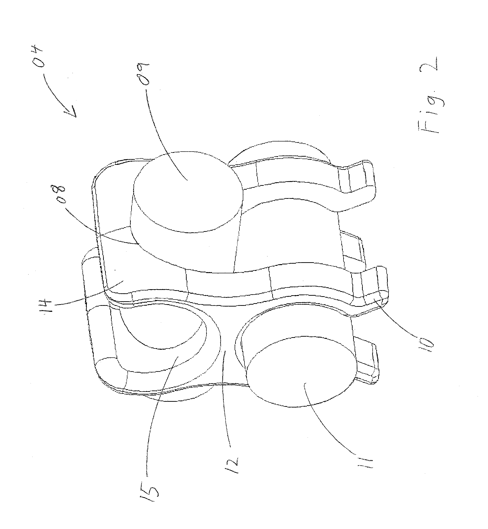
[0029]The Bar Connecting Apparatus utilizes a clip string 02 as depicted in FIG. 1. The clip string 02 is comprised of a plurality of connected individual clips 04, wherein the last clip in the series is the terminal clip 06. In the preferred embodiment, the clips 04 are comprised of plastic and each clip 04 has several components. Referring to FIG. 2, the seat 08 is adapted to engage and position a first bar 09. Below the seat 08 are a plurality of hooks 10, preferentially four hooks 10 per clip 04, which are adapted to engage and position a second bar 11 transverse to the first bar 09. The first bar 09 is also positioned on top of the second bar 11. The hooks 10 are joined by a joining portion 12, and each hook 10 has an upper body 14.

[0030]The upper body 14 combined with the upper portion of the joining portion 12 defines a cradle 15 for engaging and positioning another bar parallel to and above the second bar 11. The clip 04 can position a bar parallel to the second b...


PUM

PropertyMeasurementUnit
heightsaaaaaaaaaa
heightsaaaaaaaaaa
dimensionsaaaaaaaaaa

Abstract

A bar connecting apparatus applies clips to connect transverse bars used in reinforced concrete. A clip string is fed into the bar connecting apparatus by a clip feed assembly, so several pairs of transverse bars can be connected in rapid succession. A hammer reciprocates in the barrel of the bar connecting apparatus, and drives a clip from the barrel into engagement with the bars. An alignment head aligns the bar connecting apparatus with the transverse bars so the clips properly engage the bars.

Description

CROSS-REFERENCES TO RELATED APPLICATIONS[0001]This application is a Non-Provisional Utility application which claims benefit of co-pending U.S. Provisional Patent Application Ser. No. 60 / 860,434 filed Nov. 21, 2006, entitled “CLIP APPLYING APPARATUS” which is hereby incorporated by reference.BACKGROUND OF THE INVENTION[0002]1. Field of the Invention[0003]The present invention relates to an apparatus and method for attaching clips to connect bars, wherein the bars are used to reinforce concrete. Reinforcing bars are commonly placed within a frame where cement is to be poured, so that the reinforcing bars will become encased in the poured cement. The reinforcing bars are placed in specified positions at specified heights within the frame, so the resulting concrete is strengthened. One method used to connect the reinforcing bars before the cement is poured is clips. These clips are attached at the intersection of two bars, so the bars are held together in a fixed position. The current ...

Claims


Application Information

Patent Timeline
Patent Type & Authority Applications(United States)
IPC IPC(8): E04C5/16
CPCY10T29/53783E04C5/167E04G21/122Y10T29/49947
Inventor KODI, JON R.
Owner DAYTON SUPERIOR CORP
Learn More