Methods for reducing stress on composite structures

a composite structure and stress reduction technology, applied in the direction of machines/engines, mechanical equipment, transportation and packaging, etc., can solve the problems of foreign objects undetected in the engine, parts of the impacted blade to be torn loose from the rotor, and parts of the casing to bulge or deflect, so as to reduce the stress on the composite structure

Inactive Publication Date: 2008-05-22
GENERAL ELECTRIC CO
View PDF27 Cites 33 Cited by
  • Summary
  • Abstract
  • Description
  • Claims
  • Application Information

AI Technical Summary

Benefits of technology

[0008]Embodiments described herein generally relate to methods for reducing stress on composite structures comprising providing a primary composite structure having a circumference, providing at least one mounting flange operably connected to the primary composite structure about the circumference to form a joint, and providing a seconda

Problems solved by technology

Because engines operate in a variety of conditions, foreign objects may undesirably enter the engine.
As a result, these foreign objects may impact a fan blade and cause a portion of the impacted blade to be torn loose from the rotor, which is commonly known as fan blade out.
The loose fan blade may then impact the interior of the fan casing causing a portion of the casing to bulge or deflect.
This deformation of the casing may result in increased stresses along the entire circumference of the engine casing.
Although composite materials can provide superior strength and weight properties, and can lessen the extent of damage to the fan casing during impacts such as blade outs, designing flanges on structures fabricated from composite materials still remains a challenge.
However, issues may arise when attaching a secondary structure to an interposing flange located about the body of the composite structure, as opposed to about

Method used


Image

  • Methods for reducing stress on composite structures
  • Methods for reducing stress on composite structures
  • Methods for reducing stress on composite structures

Examples


Embodiment Construction

Integral Composite Mounting Flanges

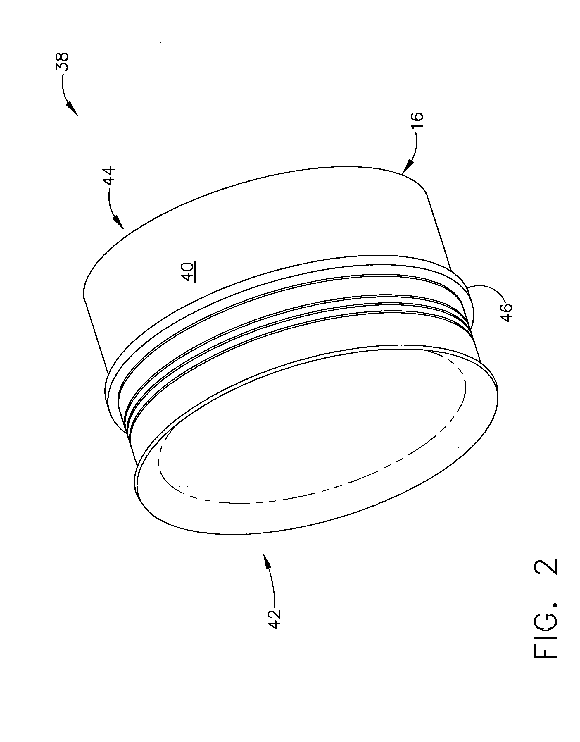
[0022]Embodiments described herein generally relate to methods for reducing stress on a composite structure that can reduce the occurrence of severe part damage to both a primary composite structure and an attached secondary structure, while concurrently helping to eliminate catastrophic part failure. While embodiments herein may generally focus on integral mounting flanges on composite fan casings of gas turbine engines, it will be understood by those skilled in the art that the description should not be limited to such. Indeed, as the following description explains, the integral mounting flange described herein may be utilized on any generally cylindrically-shaped composite structure.

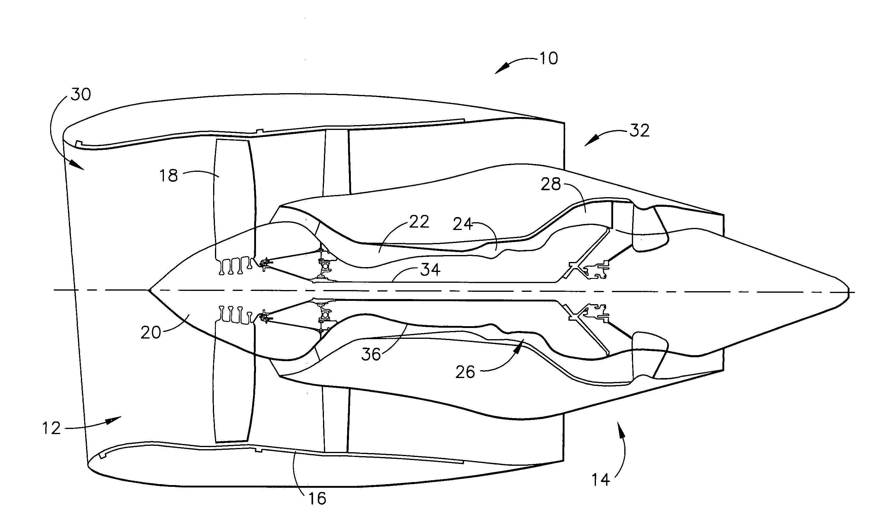
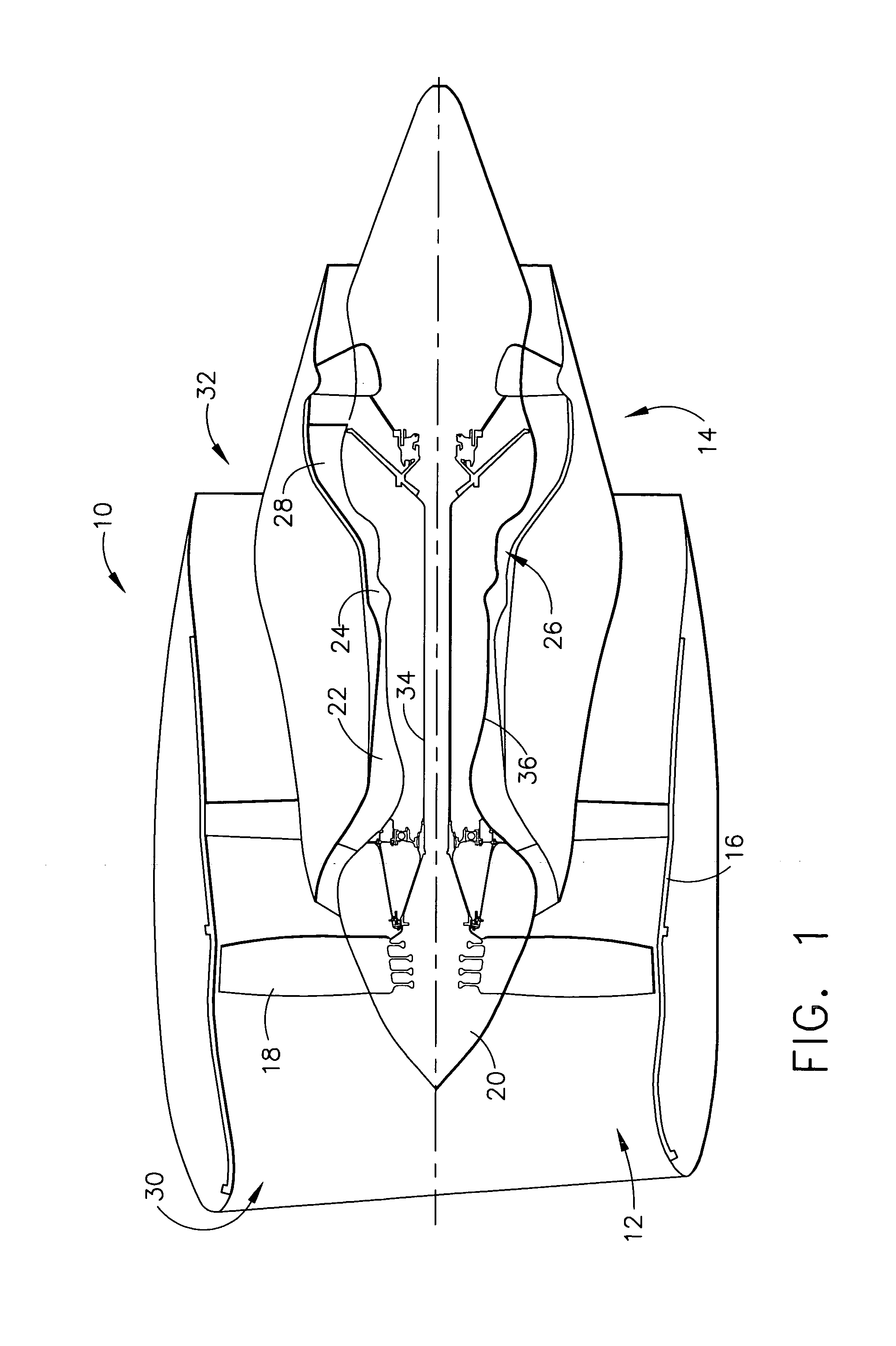
[0023]Turning to the figures, FIG. 1 is a schematic representation of one embodiment of a gas turbine engine 10 that generally includes a fan assembly 12 and a core engine 14. Fan assembly 12 may include a fan casing 16 and an array of fan blades 18 extending radiall...


PUM

PropertyMeasurementUnit
Stress optical coefficientaaaaaaaaaa

Abstract

Methods for reducing stress on composite structures involving providing a primary composite structure having a circumference, providing at least one mounting flange operably connected to the primary composite structure about the circumference to form a joint, and providing a secondary structure operably connected to the primary composite structure at the mounting flange such that when stresses on the primary composite structure exceed a maximum capacity level delamination or separation of the mounting flange from the primary structure occurs at the joint, and the secondary structure remains operably connected to the mounting flange.

Description

TECHNICAL FIELD[0001]Embodiments described herein generally relate to methods for reducing stress on composite structures. More specifically, embodiments herein generally describe methods for reducing stress on composite structures by providing a mounting flange on the composite structure that delaminates or separates, yet remains intact, after maximum stress capacity has been exceeded.BACKGROUND OF THE INVENTION[0002]In gas turbine engines, such as aircraft engines, air is drawn into the front of the engine, compressed by a shaft-mounted compressor, and mixed with fuel in a combustor. The mixture is then burned and the hot exhaust gases are passed through a turbine mounted on the same shaft. The flow of combustion gas expands through the turbine which in turn spins the shaft and provides power to the compressor. The hot exhaust gases are further expanded through nozzles at the back of the engine, generating powerful thrust, which drives the aircraft forward.[0003]Because engines op...

Claims


Application Information

Patent Timeline
IPC IPC(8): E04C2/38
CPCF01D21/045F01D25/005F01D25/243F05D2300/603Y02T50/672Y10T428/1314Y10T428/1317Y10T29/4932F01D25/24F01D25/26F01D25/14Y02T50/60
Inventor XIE, MING
Owner GENERAL ELECTRIC CO
Why Eureka
Try Eureka