
Method for forming a composite support beam

a technology of composite support beams and beams, which is applied in the field of forming composite support beams, can solve the problems of limited capacity to meet these requirements, laborious current method of fabrication of “z” channels, and beam forming operation of “z” channels, etc., and achieve the effect of improving formation operations

Active Publication Date: 2008-05-22
THE BOEING CO
View PDF11 Cites 19 Cited by
  • Summary
  • Abstract
  • Description
  • Claims
  • Application Information

AI Technical Summary

Benefits of technology

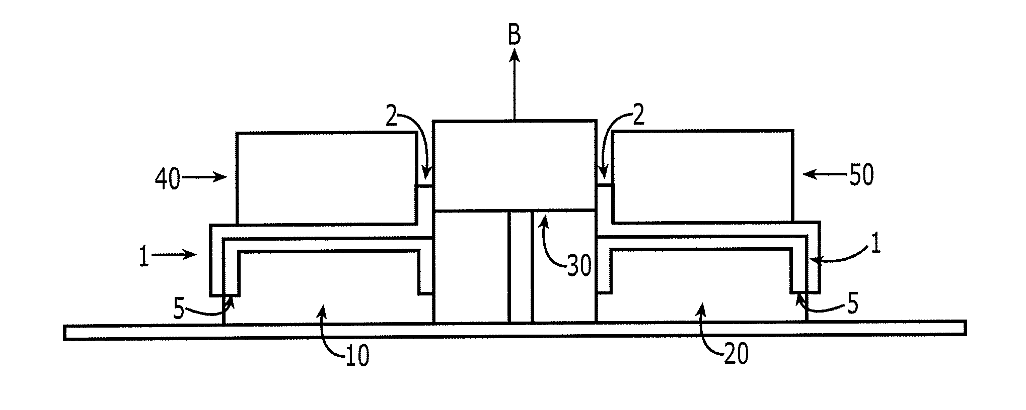
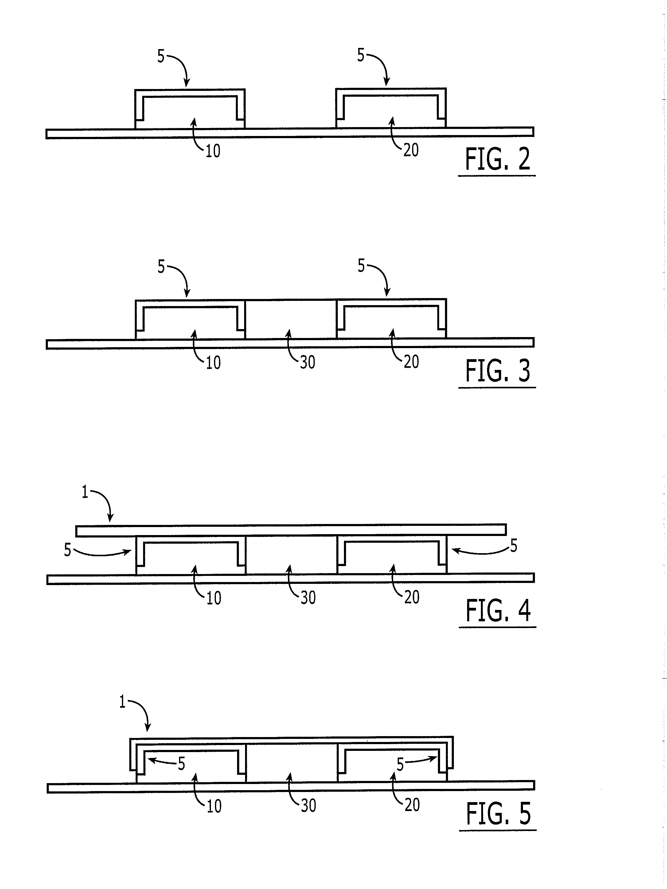
[0010]Another embodiment provides a method for forming a pair of support beams, such as J-beams. The method includes supporting first and second C-shaped composite charges upon first and second forming tools, respectively. The method further includes placing an additional charge upon at least portions of the first and second charges and a third forming tool positioned between the first and second forming tools. In addition, the method includes positioning a fourth forming tool proximate the first forming tool and a fifth forming tool proximate the second forming tool. The third forming tool can be heated to enhance formation operations. The method may also include cutting in two the additional charge before moving the third forming tool. The method includes moving the third forming tool toward the additional charge to bend portions of the additional charge and thereby form the pair of support beams. In addition, the method may include curing the support beams after the third forming tool is moved. The method may include bending a first end portion and a second end portion of the additional charge about the first and second forming tools, respectively.

Problems solved by technology

Prior and emerging art have provided limited capabilities to satisfy these requirements.
When using composite material, one difficult challenge in forming a J-beam is the forming operation of the “Z” channel.
Unfortunately, the current method of fabrication of the “Z” channel is labor intensive.
As such, the speed of production is slow, and the efficiency is low.
The labor intensive fabrication process drives up production costs.

Method used


Image

  • Method for forming a composite support beam
  • Method for forming a composite support beam
  • Method for forming a composite support beam

Examples


Embodiment Construction

[0023]The embodiments will now be described more fully hereinafter with reference to the accompanying illustrations, in which some, but not all embodiments of the inventions are shown. Indeed, these embodiments may be embodied in many different forms and should not be construed as limited to the embodiments set forth herein; rather, these embodiments are provided so that this disclosure will satisfy applicable legal requirements. Like numbers refer to like elements throughout.

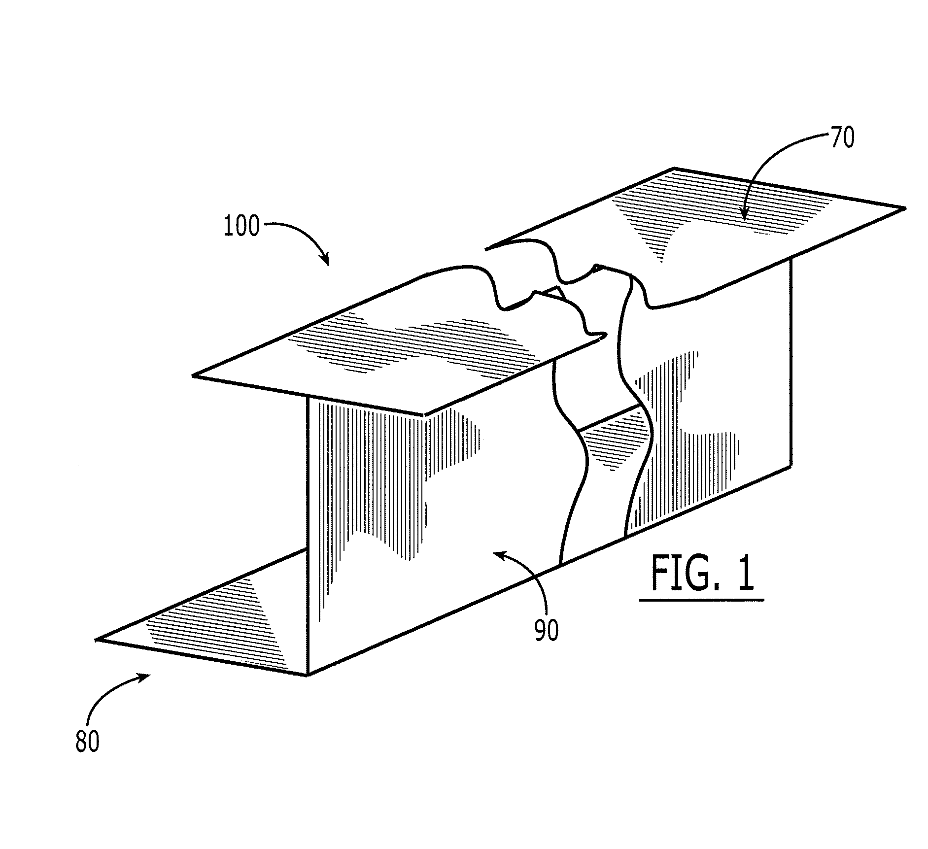
[0024]Referring now to FIG. 1, there is shown a support beam and, more particularly, a J-beam 100 with a flat cap 70, a flange 80, and a web 90 extending therebetween. J-beams 100 can be formed of composites, metals, and other materials. In conjunction with the fabrication methods described below, J-beams 100 formed of composite materials, such as a ply or sheet of prepreg material, which may include a matrix of graphite fibers preimpregnated with a conventional resin, will be primarily described. J-beams 100 c...


PUM

PropertyMeasurementUnit
chargeaaaaaaaaaa
strengthaaaaaaaaaa
speedaaaaaaaaaa

Abstract

A method of forming a support beam is provided. One exemplary method of forming a support beam includes supporting a C-shaped charge upon a first forming tool and placing an additional composite charge upon at least a portion of the C-shaped charge and a second forming tool proximate the first forming tool. The method of forming a support beam further includes positioning a fixed forming tool proximate a first portion of the additional charge and bending the additional charge about the forming tool.

Description

BACKGROUND[0001]1) Technical Field[0002]Embodiments of the disclosure relate to methods for forming support beams and, more specifically, to methods of forming composite J-beams.[0003]2) Description of Related Art[0004]One part that is widely used by aircraft and other structures is a support beam. One type of support beam is a J-beam, which is used for cargo floor beams, wing spars, and various other structures. Composite materials are often selected to form support beams, such as J-beams, since composite materials may be a lighter alternative to metals while still maintaining sufficient strength. Composite J-beams may be formed from an assemblage of “C” and “Z” channels. Typically, composite “C” channels are formed, among other ways, with an elastomeric membrane hot forming machine. Composite “Z” channels are usually fabricated by hand lay up of a resin-impregnated fibrous material on a “Z” channel tool.[0005]The drive for increased speed and efficiency and a desire to reduce fabr...

Claims


Application Information

Patent Timeline
Patent Type & Authority Applications(United States)
IPC IPC(8): B21D47/01B29D99/00
CPCB29D99/0014B29C70/345
Inventor DEPASE, EDOARDO P.WILLDEN, KURTISZENKNER, GRANT
Owner THE BOEING CO
Learn More