Voting machine storage and transport cart with improved security

a technology for transporting carts and voting machines, applied in the field of accessories for voting devices, can solve the problems of difficult to deliver, move in, monitor, remove and return, and paper balloting is difficult for mobility impaired, vision impaired or non-english speakers, etc., to achieve restrain the on-board equipment, facilitate and secure transportation, and maximize strength and usability

Active Publication Date: 2008-05-22
CASTO & HARRIS +1
View PDF7 Cites 15 Cited by
  • Summary
  • Abstract
  • Description
  • Claims
  • Application Information

AI Technical Summary

Benefits of technology

[0020]According to the present invention, the above-described and other objects are accomplished by providing a specially-adapted utility cart for storage and / or transport of voting devices in a more convenient and secure manner. The utility cart is capable of supporting a touch-screen voting terminal, separate optical scan voting tabulator and ballot box, multiple (collapsible) voting booths, and an area to store the accessory items required by the voter precinct. The touch-screen voting terminal is seated atop a sliding shelf, and the optical scan voting tabulator seated atop the ballot box are installed in a large compartment, the voting booths in their own compartment, and the accessory items in their own compartment (optionally a plastic, metal or corrugated tote box can be used to further combine and constrain these accessory items). These and other equipment may be wheeled into usable positions in the precinct, the voting booths removed and set up, all such equipment plugged into an optional on-board power strip, and the precinct is then ready for voting traffic. The touch-screen voting terminal is deployed face-forward at waist-level on the slide-out shelf for easy wheelchair and / or any other voter access thereto. The cart is generally formed with a pair of opposing side-rails defined by contiguous tubing bent in a closed rectangular loop with a full-height vertical reinforcing strut running from top to bottom of the loop. A plurality of lateral struts join the side-rails together. An optional rectangular deck may be secured atop the bottom-most struts and side-rails, but the open support of the side-rails will suffice. Four castors (with optional brake locks) are mounted beneath the bottom side rails, and the optional powerstrip is mounted on one of the lateral struts. The extensible shelf is mounted on roller-brackets between the side-rails and is extensible from one end thereof. In addition, a plurality of additional wires or bars interrupt the open rectangle of the side rails to restrain the on-board equipment. Also, optional securement belts are employed, one for holding the voting terminal onto the shelf, and a second securement belt removably attachable across the extensible shelf for securing the touch-screen terminal in the cart. All the loaded equipment is fully restrained against lateral motion, and yet all equipment is given full access to their control panels, doors, etc. Moreover, the particular design maximizes strength and usability, and yet keeps weight to a minimum with a framework that is as light weight as possible. In addition to the securement belt the sliding shelf is equipped with additional mechanical means of restraining and locking the shelf in either the stored or use (extended) position. This may be accomplished by use of easily accessible turn locks, thumb screws or other mechanical means.

Problems solved by technology

Moreover, voting devices are extremely heavy, requiring a very robust utility cart, and they must be thoroughly accessible by persons, inclusive of physically disabled persons, from outside the cart.
Paper balloting can be hard for mobility impaired, vision impaired or non-English speakers to use.
It is not an easy task for precinct workers to deliver, move in, set up, monitor, remove and return to storage this much voting equipment.
Such carts take no security precautions, and do not facilitate on-board access to the equipment.
Since the equipment is not accessible while on the cart, it must be off-loaded and the cart removed for voting.

Method used


Image

  • Voting machine storage and transport cart with improved security
  • Voting machine storage and transport cart with improved security
  • Voting machine storage and transport cart with improved security

Examples


first embodiment

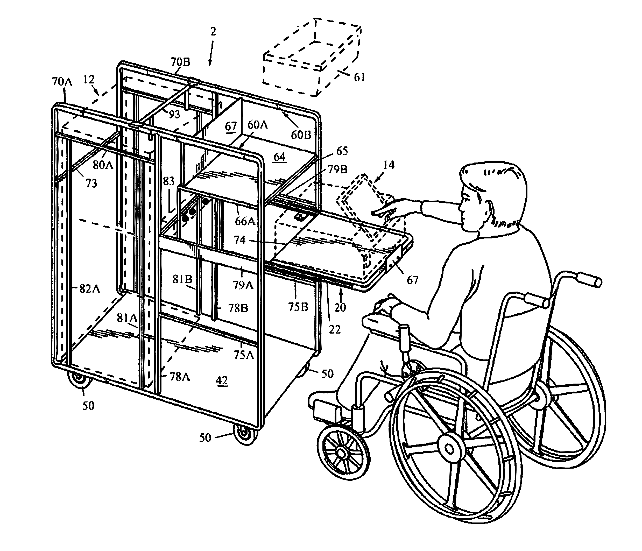
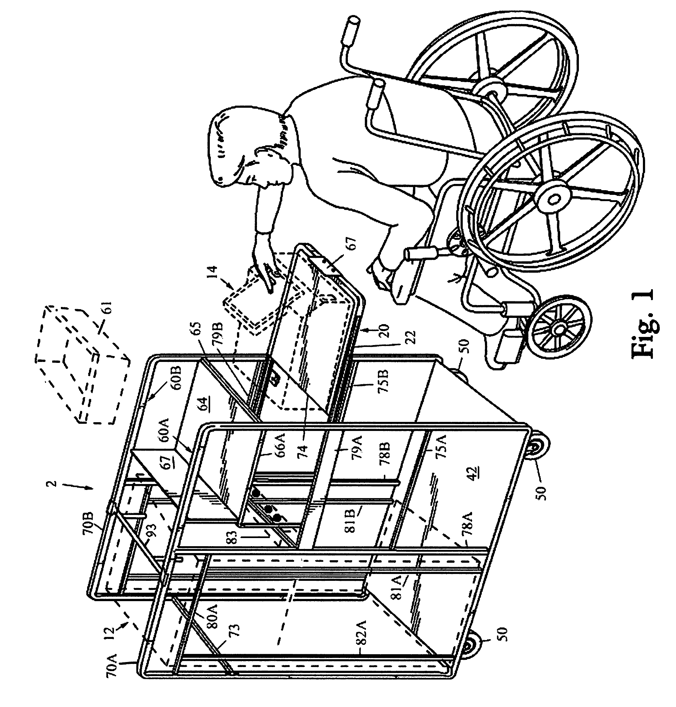
[0034]FIG. 1 illustrates the utility cart 2 and carrying the Optical scan voting tabulator 12 (here an ES&S Model M100 Ballot Counter and AutoMARK™ voter assist terminal in a fixed position, with voter assist terminal 14 (here an AutoMARK™ voter assist terminal likewise shown in dotted lines) seated on slide out shelf 20 in an extended position to deploy the touch-screen display.

[0035]FIG. 2 is a top perspective view of the utility cart 2 as in FIG. 1 with touch-screen display of the voter assist terminal 14 folded and the slide out shelf 20 retracted to stow the voter assist terminal 14.

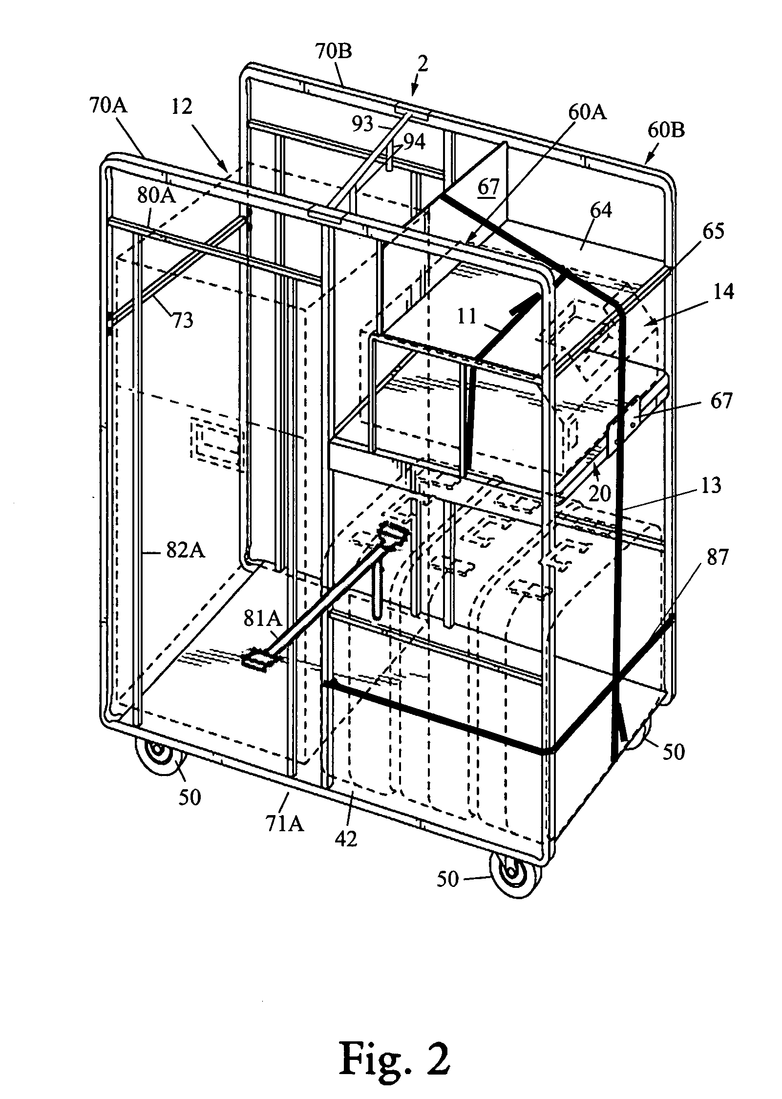
[0036]FIG. 3 is a left side perspective view of the utility cart 2 as in FIGS. 1-2 which better illustrates the framework, and FIG. 4 is a right side perspective view. With collective reference to FIGS. 1-4, the cart 2 generally comprises a substantially rectangular tubular framework bounded by opposing rectangular side-rail assemblies 60A and 60B on either side. The side-rail assemblies 60A and 60...

embodiment 120

[0056]Operation of the voter cart embodiment 120 is in all other respects identical to cart 2. The layout of the cart 120 affords excellent voting privacy since an election official scanning a ballot at one end cannot see the voter's inputs to the voting terminal at the other end of the cart 120.

[0057]One skilled in the art should understand that other accessories are possible in addition to those shown, which are illustrative only and are not intended to be self limiting.

[0058]For example, to further enhance privacy an optional privacy screen 97 may be employed as shown in FIG. 11. The privacy screen 97 comprises a five-walled enclosure with open viewing aperture directed outwardly toward the voter. The privacy screen is preferably removably attached by Velcro™ or the like directly to the pull-out shelf assembly 20 overtop the voting terminal to shield the voter's actions.

[0059]In all such cases the utility carts 2, 120 according to the present invention provide a storage and trans...


PUM


Abstract

A voter cart capable of supporting a voting terminal, optical scan ballot counter and ballot box, and multiple (collapsible) voting booths in a portable, fully usable and secure configuration. The cart is generally formed with a pair of opposing side-rails joined together in a spaced-apart configuration and mounted on castors, and a plurality of reinforcing struts between and amongst the side rails. The touch-screen voting terminal is seated atop a sliding shelf mounted on roller-brackets between the side-rails and extensible from one end thereof at waist-level for easy wheelchair and/or any other voter access thereto. All the loaded equipment is fully restrained against lateral and vertical motion, and yet all equipment is given full access to their control panels, doors, etc. Moreover, the particular design maximizes strength and usability, and yet keeps weight to a minimum with a framework that is as light weight as possible.

Description

CROSS-REFERENCE TO RELATED APPLICATION(S)[0001]The present application derives priority from U.S. Provisional application Ser. No. 60 / 856,701 filed 22 Nov. 2006.BACKGROUND[0002]a. Field of Invention[0003]The invention relates to accessories for voting devices and, more particularly, to a specially-adapted utility cart for storage and / or transport and / or use of voting devices in a more convenient and secure manner.[0004]b. Background of the Invention[0005]There are a myriad of existing storage and transport carts currently in use for a wide variety of different applications. Some of these carts are adapted for carrying high-value electronic equipment, and others carry confidential high-security items. Utility carts for voting devices must combine both sets of attributes inasmuch as voting devices are high-value devices and require considerable security precautions. Moreover, voting devices are extremely heavy, requiring a very robust utility cart, and they must be thoroughly accessib...

Claims


Application Information

Patent Timeline
Patent Type & Authority Applications(United States)
IPC IPC(8): G07C13/00
CPCG07C13/00
Inventor WILSON, JOSEPHABEL, GARY V.
Owner CASTO & HARRIS
Why Eureka
Try Eureka