Eureka AIR delivers breakthrough ideas for toughest innovation challenges, trusted by R&D personnel around the world.

Pseudo-random number demodulation circuit of receiving device of wireless communication system

Inactive Publication Date: 2008-05-22
CHUNG-SHAN INSTITUTE OF SCIENCE & TECHNOLOGY; MINISTRY OF NATIONAL DEFENSE
View PDF6 Cites 8 Cited by
  • Summary
  • Abstract
  • Description
  • Claims
  • Application Information

AI Technical Summary

Benefits of technology

[0008]The present invention is directed to a pseudo-random number demodulation circuit of receiving device of wireless communication system. It has a first demodulator, a splitter, and a second demodulator. The first demodulator demodulates all pilot subcarriers and all data subcarriers of the symbol data in the receiving device according to multiple first PN. The splitter splits the pilot subcarriers and the data subcarriers from the demodulated symbol data, and the data subcarriers are transmitted to the second demodulator. The second demodulator demodulates the output data subcarriers of the splitter according to multiple second PN. Therefore, the receiving device of the present invention can enhance the performance of multiple symbol data. Further, the receiving device of the present invention has a FFT unit, a phase-shift estimate unit, and a data detector. The FFT unit can fast transform and input symbol data to the receiving device. The phase-shift estimate unit can produce multiple corresponding phase-shift values according to the pilot subcarriers. The data detector detects the data subcarriers for producing the corresponding data according to the phase-shift value.

Problems solved by technology

However, not every transmission data is counted in this way.
More complicated determination always increases the complexity of the demodulation circuit, and further decreases the performance of the demodulation circuit.

Method used


Image

  • Pseudo-random number demodulation circuit of receiving device of wireless communication system
  • Pseudo-random number demodulation circuit of receiving device of wireless communication system
  • Pseudo-random number demodulation circuit of receiving device of wireless communication system

Examples


Embodiment Construction

[0015]Each of the forgoing examples merely illustrates some applications for the present invention. It is understood that the invention is not limited to such embodiments. Other features and advantages of the present invention will become apparent from the following detailed description of the invention made with reference to the accompanying drawings.

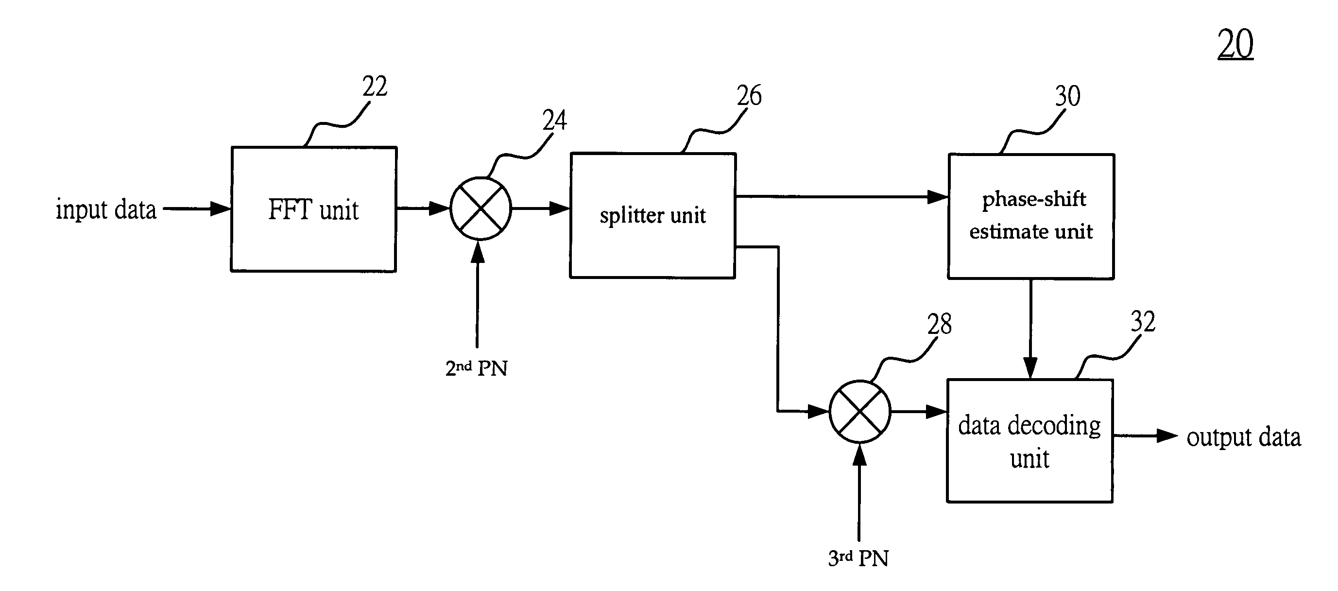
[0016]The present invention relates to a pseudo-random number (PN) demodulation circuit of a receiving device for a wireless communication system as well as provides a simplifier demodulation circuit. More, the present invention can fast demodulate multiple symbol data which have been modulated by a transmitting device of a wireless communication system according to multiple PN. Each symbol data includes a header data and a payload data. The header data and the payload data individually include multiple pilot subcarriers and multiple data subcarriers. The demodulation circuit of the present invention, therefore, can be used in differen...


PUM


Abstract

The present invention relates to a pseudo-random number demodulation circuit of receiving device of wireless communication system. More particularly, it can demodulate the symbol data transmitted from a transmitting device for a wireless communication system. The transmitting device modulates multiple pilot subcarriers and multiple data subcarriers of the symbol data according to a first PN. The present invention uses a first demodulator demodulates all pilot subcarriers and data subcarriers of the symbol data according to a second PN. Further, a splitter splits the symbol data to the pilot subcarriers and the data subcarriers. More, a second demodulator is used to demodulate the data subcarriers according to a third PN. Therefore, the present invention can demodulate the pilot subcarriers and the data subcarriers which have not been modulated.

Description

FIELD OF THE INVENTION[0001]The present invention relates to a pseudo-random number demodulation circuit of receiving device of wireless communication system. More particularly, it is directed to pseudo-random number (PN) demodulation circuit of a receiving device for a wireless communication system.BACKGROUND OF THE INVENTION[0002]The development of communication systems currently is toward to a century of wireless communication systems. Most conventional wireless communication systems use the demodulation circuit of the receiving device as shown in FIG. 1 to modulate the output data of the transmitting device according to a pseudo-random number (PN). Multi-Band Orthogonal Frequency Division Multiplexing Ultra Wide Band (MB-OFDM UWB) system is one example in the present invention. Please refer to FIG. 1. It is a block diagram showing one conventional transmitting device for a wireless communication system. As can be seen from FIG. 1, the conventional transmitting device 10 has a fi...

Claims


Application Information

Patent Timeline
IPC IPC(8): H03D1/00H04L27/06
CPCH04L27/2647
Inventor CHUANG, YU-MINYEH, FU-MINDENG, JUINN-HORNG
Owner CHUNG-SHAN INSTITUTE OF SCIENCE & TECHNOLOGY; MINISTRY OF NATIONAL DEFENSE
Why Eureka
Eureka Blog
Learn More