

Fluid pump
a technology of fluid pump and pump body, which is applied in the direction of pump components, piston pumps, non-positive displacement fluid engines, etc., can solve the problems of vibration of the engine, decrease in the durability and reliability of the semiconductor device, and achieve the effect of effectively preventing the semiconductor device from reaching a high temperatur
- Summary
- Abstract
- Description
- Claims
- Application Information
AI Technical Summary
Benefits of technology
Problems solved by technology
Method used
Image

Examples
first embodiment
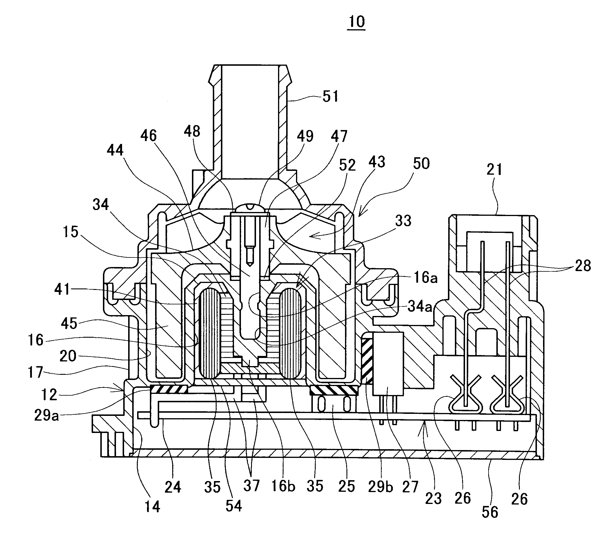
[0026]A fluid pump 10 of a first embodiment of the present teachings will be described. The fluid pump 10 can be utilized to circulate cooling water for cooling an engine of a motor vehicle, and can be disposed in an engine room of the motor vehicle. As shown in FIG. 1, the fluid pump 10 comprises a lower body 12, and an upper body 50 that is fixed to the lower body 12. The lower body 12 and the upper body 50 are both molded integrally from resin material.
[0027]A cylindrical convex part 15 is formed at an upper part of the lower body 12 (at the left side in FIG. 1). A shaft attaching hole 16a is formed in a center of the convex part 15. A lower end of a shaft 46 is fixed in the shaft attaching hole 16a. An upper end part of the shaft 46 protrudes upward beyond an upper surface of the convex part 15. An impeller 43 is attached in a manner allowing rotation to the upper end part of the shaft 46. A cylinder-shaped outer wall 17 is formed at an outer circumference of the convex part 15....
second embodiment
[0048]Next, a fluid pump 100 of a second embodiment of the present teachings will be described. The fluid pump 100 can also be utilized to circulate cooling water for cooling an engine. As shown in FIG. 4, the fluid pump 100 is an inner rotor fluid pump. The fluid pump 100 comprises a lower body 112, an upper body 150 that is fixed to an upper end of the lower body 112, and a cover 116 that is fixed to a lower end of the lower body 112.
[0049]A concave part 118 is formed in approximately the center of an upper part of the lower body 112, and a convex part 121 is formed at an outer side of the concave part 118. Seen from above, the convex part 121 has a ring shape surrounding the concave part 118. The convex part 121 and the concave part 118 are disposed concentrically. A substrate housing part 114 is formed within the lower body 112. A stator housing part 121a is formed within the convex part 121. A lower end of the stator housing part 121a communicates with the substrate housing par...
third embodiment
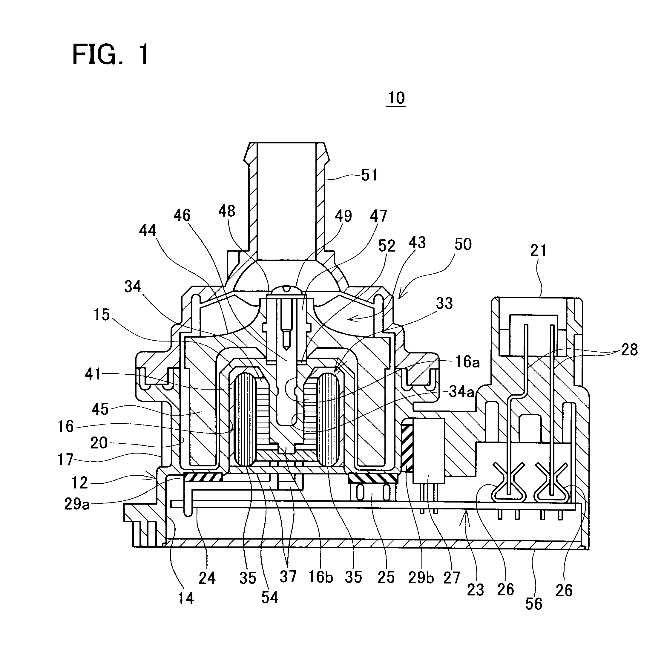
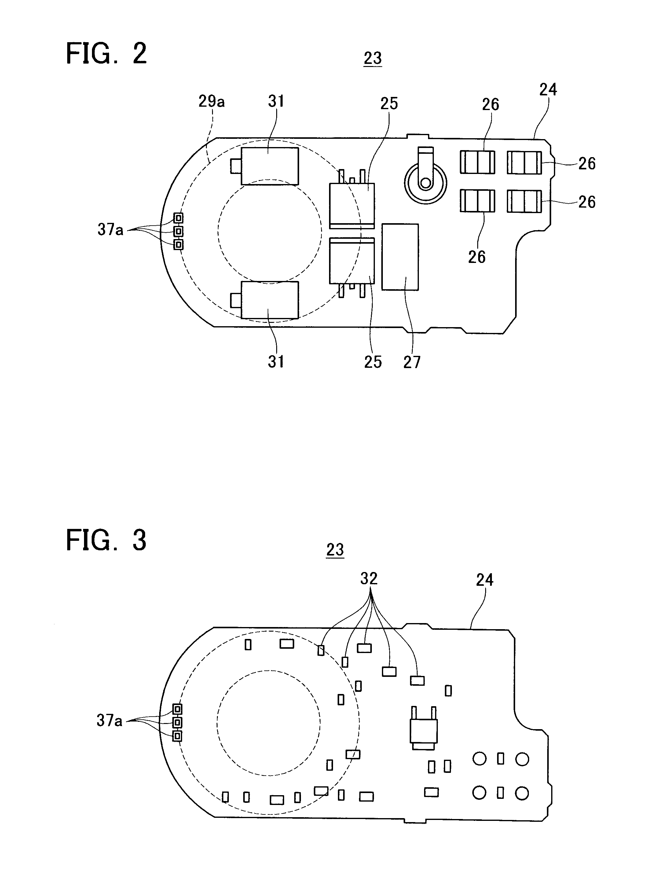
[0054]Next, a fluid pump 200 of a third embodiment of the present teachings will be described. The fluid pump 200 can also be utilized to circulate cooling water for cooling an engine. As shown in FIG. 5, the fluid pump 200 is an outer rotor fluid pump. The fluid pump 200 comprises a lower body 212, an upper body 250 that is fixed to an upper end of the lower body 212, and a cover 216 that is fixed to a lower end of the lower body 212. An impeller 243 is disposed in an inner space (i.e., pump chamber) 220 surrounded by the lower body 212 and the upper body 250. A circuit substrate 223 is housed in the lower body 212. A ring-shaped sheet member 229 makes contact in a planar manner with an upper surface of a substrate 224 of the circuit substrate 223. An upper surface of the sheet member 229 makes contact in a planar manner with a wall of the lower body (specifically, a wall facing a lower end surface of an impeller 243). The sheet member 229 also has a high degree of thermal conducti...
PUM
 Abstract
Description
Claims
Application Information