
Method and apparatus for backup and restore in a dynamic chunk allocation storage system

a dynamic chunk allocation and storage system technology, applied in the field of storage systems, can solve the problems of large amount of unused physical data blocks, no backup or restore method disclosed for protecting data, and large amount of backed-up data wasted spa

Active Publication Date: 2008-05-22
HITACHI LTD
View PDF5 Cites 82 Cited by
  • Summary
  • Abstract
  • Description
  • Claims
  • Application Information

AI Technical Summary

Benefits of technology

The invention is about a way to backup and restore data on a storage system that uses dynamic chunk allocation. This method helps to avoid wasting storage capacity when restoring a backup image. Overall, the invention improves the efficiency and effectiveness of data backup and restore in a DCA storage system.

Problems solved by technology

Thus, conventional storage systems that do not incorporate dynamic capacity allocation capability usually have large amounts of unused physical data blocks (i.e., wasted physical blocks) allocated to volumes in the system even though no data is stored in those blocks.
However, this prior art does not disclose any backup or restore methods for use in protecting data in such thin-provisioned volumes in DCA storage systems.
However, when this conventional backup technique is applied to a volume on a storage system that utilizes DCA capability, the backup program attempts to read data from areas (segments) of the volume that have not yet had physical storage space allocated to them.
Consequently, on the backup image of the volume, a large amount of the backed-up data might be wasted space because normally whole volume images are stored during data backup using conventional backup software.
Thus, the whole backup image is used to rebuild the volume, which defeats the purpose of dynamic chunk allocation capability because the backup computer issues write commands to all the allocated address blocks in the volume, thereby allocating blocks to the volume even though they are filled with null data of the default data pattern, which can result in unnecessary wasting of large amounts of physical storage space.

Method used


Image

  • Method and apparatus for backup and restore in a dynamic chunk allocation storage system
  • Method and apparatus for backup and restore in a dynamic chunk allocation storage system
  • Method and apparatus for backup and restore in a dynamic chunk allocation storage system

Examples


first embodiments

ion

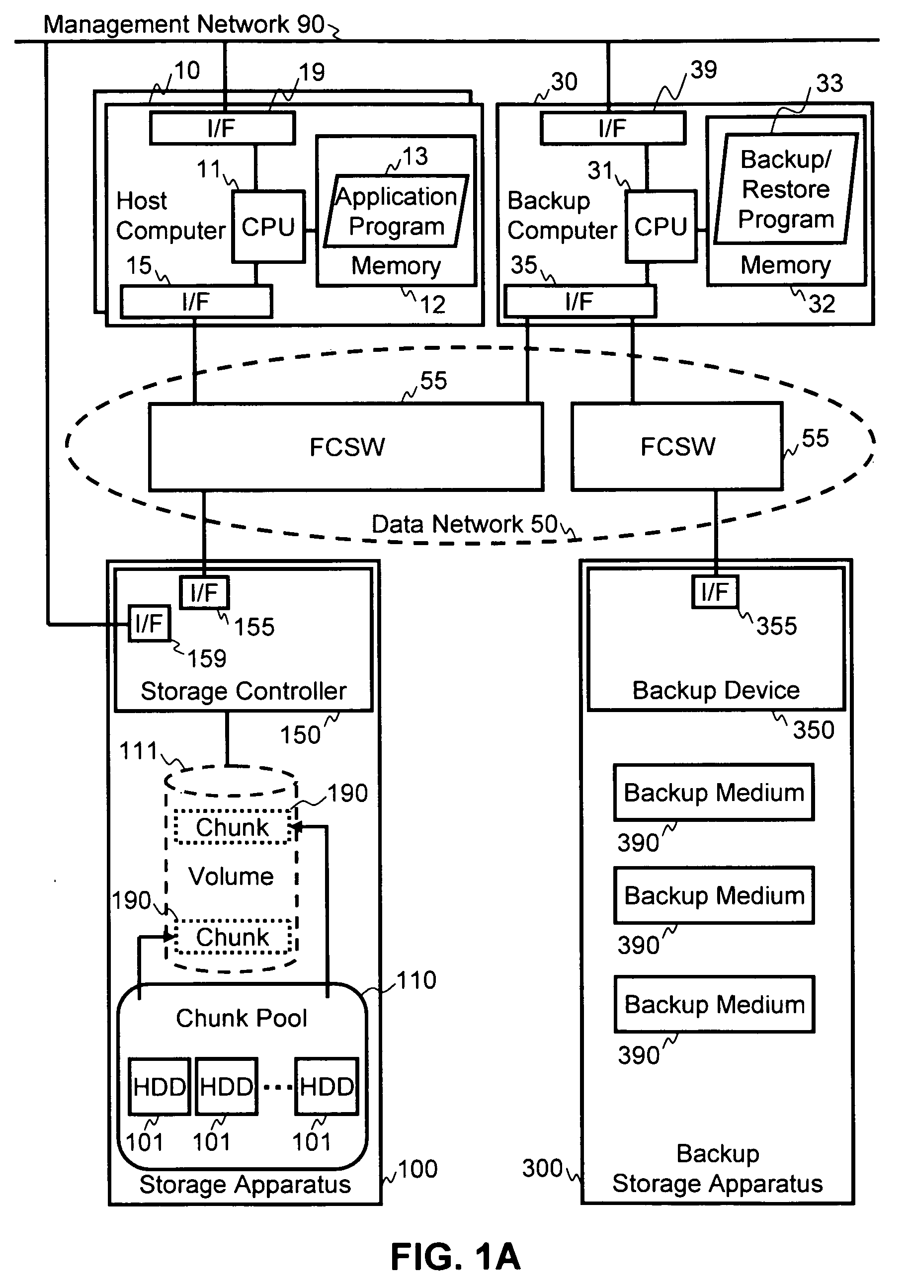
[0036]FIG. 1A illustrates an example of an information system overview in which the methods of the invention may be applied. The information system includes one or more host computers 10, or other device, that is able to store data to a storage apparatus 100 via a data network 50. The host computer 10 is able to issue write commands and read commands to the storage apparatus 100. Thus, data generated by the host computer 10 may be written to the storage apparatus 100 for storage, and data in the storage apparatus 100 may be read out to the host computer 10. At least one backup computer 30 is connected to the storage apparatus 100 via the data network 50, and is also connected to a backup storage apparatus 300 via the data network 50.

[0037]Storage apparatus 100 includes a storage controller 150 in communication with one or more storage devices, such as hard disk drives (HDDs) 101, or other equivalent storage devices, such as optical drives, solid state storage, etc. Storage contro...

second embodiments

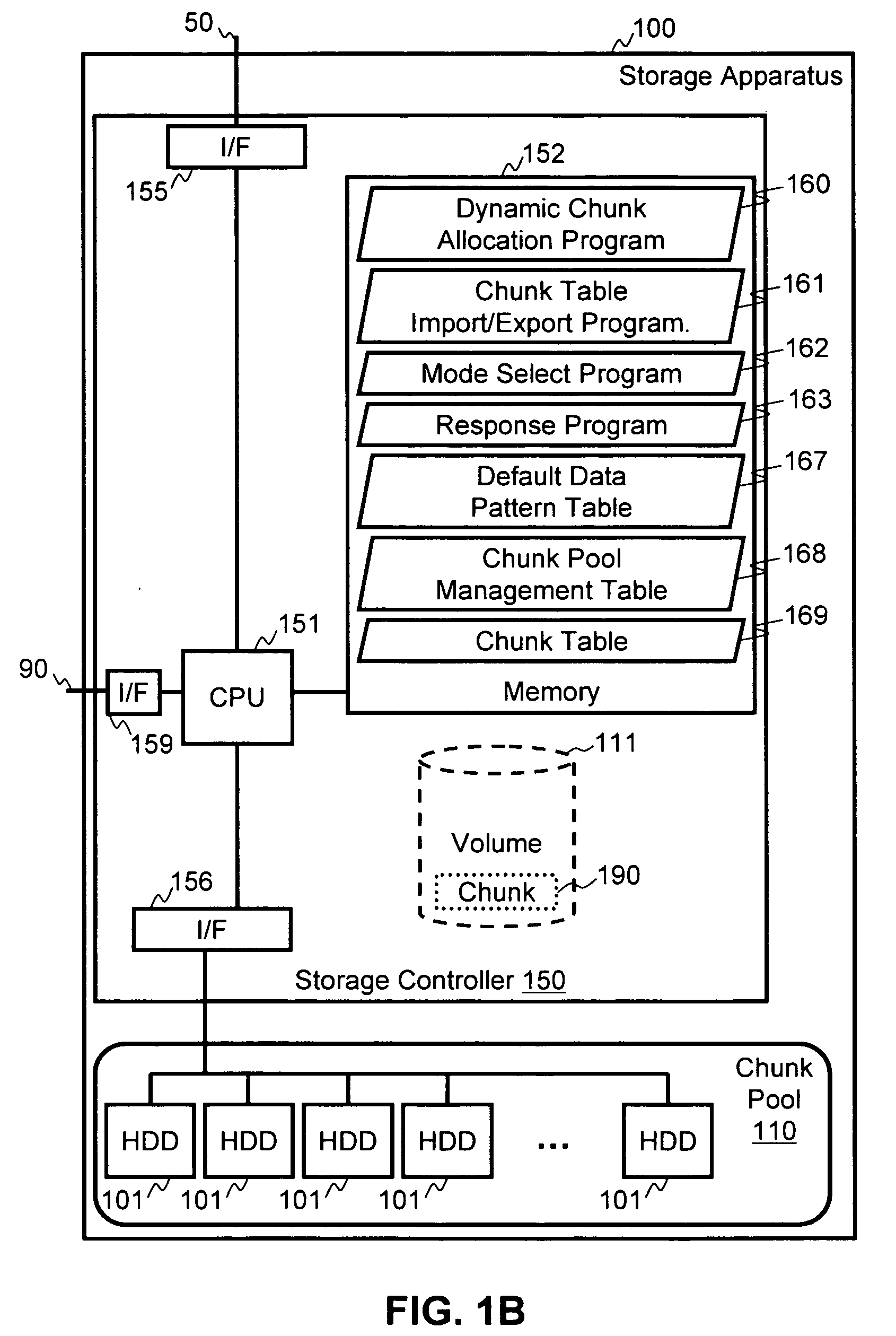
[0127]The second embodiments can use the same system configuration as described above with respect to FIG. 1A. Accordingly, only the differences in function will be described. FIG. 13 illustrates a process flow carried out by the dynamic chunk allocation program 160 in the second embodiments. In the second embodiments, the default data pattern table 167 may hold, for example, an all-zero data pattern. Although, any other default data pattern can also be applied. Further, each volume may have its own default data pattern table 167, or plural volumes may share the same default data pattern table 167.

[0128]In the second embodiments, the DCA storage apparatus 100 includes a “void data” (default data) detecting step in the dynamic chunk allocation program. During a restore operation, when the backup computer restores the backup image, the DCA storage apparatus 100 receives a WRITE command with the restore data, as described above with respect to the first embodiments. However, instead of...

third embodiments

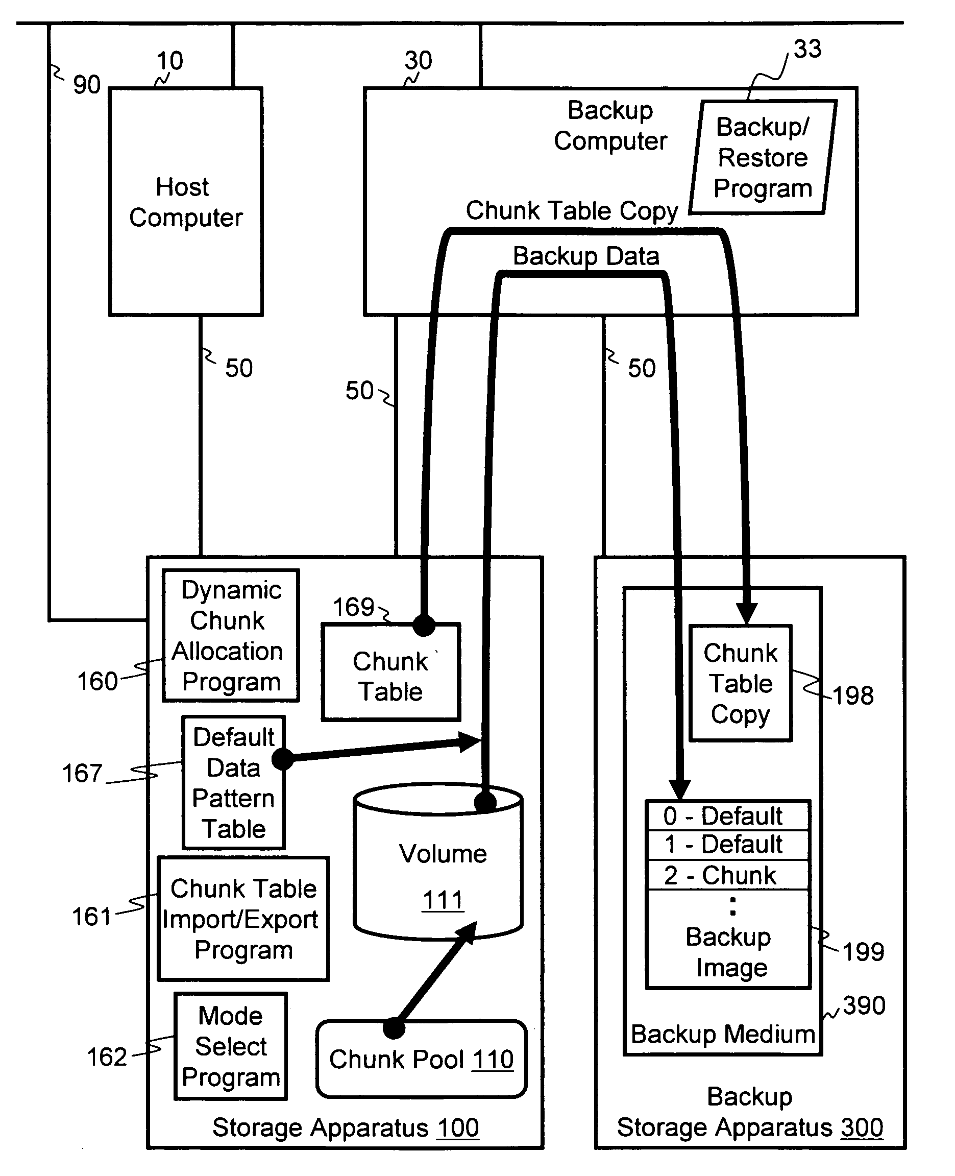
[0143]In the third embodiments, the DCA storage system includes the mode select program 162 and a “no data transfer” step. In these embodiments, the DCA storage apparatus 100 is set to a “backup mode” before beginning a backup operation. In the backup mode, the DCA storage apparatus 100 responds with a no data transfer condition to the backup computer when a read occurs on a segment of the volume that has not yet had storage chunks allocated to it. Then, during a restore operation, data is restored only to segments of the volume that were stored in the backup image. FIG. 14 illustrates a process flow in the response program 163 for the third embodiments, while FIGS. 15 and 16 illustrate the process flow of the backup / restore program 33, with FIG. 15 illustrating the backup operation and FIG. 16 illustrating the restore operation. In addition, FIG. 18 illustrates a conceptual diagram of the backup operation of the third embodiments.

[0144]Backup

[0145]As illustrated in FIG. 14, in the ...


PUM


Abstract

Backup and restore operations are made possible in a storage system that has dynamic chunk allocation (DCA) capability. In a DCA storage system, a chunk of physical storage area is not allocated to a segment of a volume until a write command is received targeting the segment of the volume. During a restore operation of the volume in the DCA storage system, the wasting of storage capacity when a backup image of the volume is restored is mitigated by preventing allocation of physical storage areas to segments of restore data that are only void data.

Description

BACKGROUND OF THE INVENTION[0001]1. Field of the Invention[0002]The present invention relates generally to storage systems.[0003]2. Description of Related Art[0004]To reduce the waste of physical blocks in storage volumes, storage systems have been developed that utilize dynamic chunk allocation (DCA) capability (also referred to as “dynamic capacity allocation” or “thin provisioning storage systems”). Under DCA technology, a logical volume is allocated for use by one or more host computers for storing data, but no physical blocks of storage are initially allocated to the volume. Instead, when the storage system receives a write command from a host directed to an area of the volume that has not yet had physical storage capacity allocated to it, the storage system allocates an area of physical storage space (commonly referred to as a storage “chunk”) from a pool of available physical storage areas (i.e., a storage chunk pool). The chunk of storage capacity is a physical storage area ...

Claims


Application Information

Patent Timeline
Patent Type & Authority Applications(United States)
IPC IPC(8): G06F12/16
CPCG06F11/1451G06F11/1469G06F11/1456
Inventor KANEDA, YASUNORIHARA, JUNICHIYAMAMOTO, AKIRA
Owner HITACHI LTD
Learn More