Gravity Gradiometer

a gravity gradiometer and gravity technology, applied in the field of gravity gradiometers, can solve the problems of difficult and expensive manufacturing of coils, and achieve the effect of less expensive manufacturing

Inactive Publication Date: 2008-05-29
TECHNOLOGICAL RESOURCES
View PDF39 Cites 43 Cited by
  • Summary
  • Abstract
  • Description
  • Claims
  • Application Information

AI Technical Summary

Benefits of technology

[0009]The object of the invention is to provide a transducer in a gravity

Problems solved by technology

Typically the sensing coils are required to have a large number of turns which can make the coils difficult and exp

Method used


Image

  • Gravity Gradiometer
  • Gravity Gradiometer
  • Gravity Gradiometer

Examples


Embodiment Construction

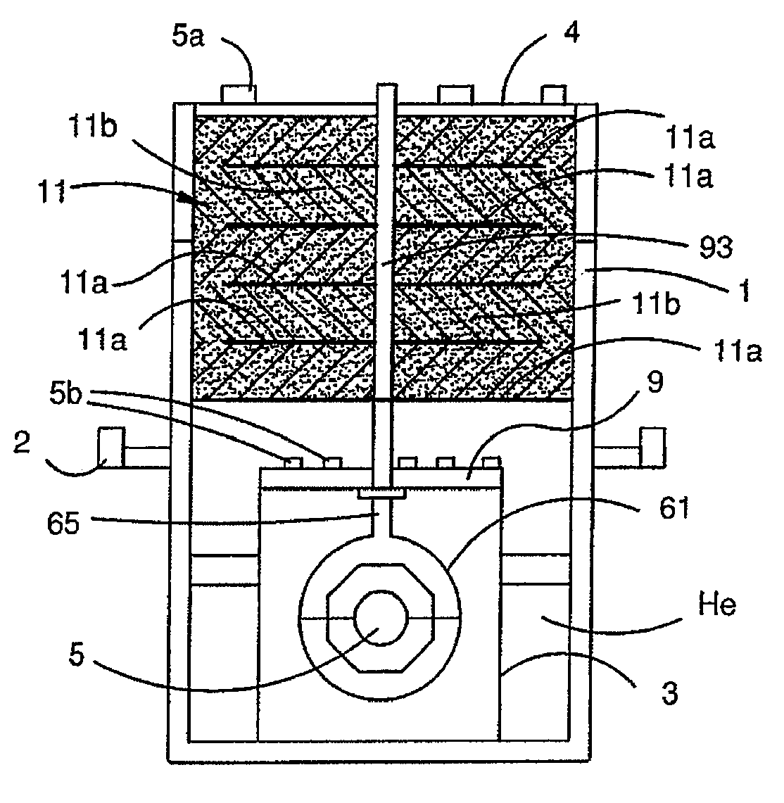
[0072]FIG. 1 is a schematic view of a gravity gradiometer according to one embodiment of the invention.

[0073]The gradiometer shown in FIG. 1 comprises a double walled Dewar 1 which is supported in an external platform 2. The external platform 2 enables adjustment of the Dewar and therefore the contents of the Dewar about three orthogonal axes. The external platform 2 is generally known and its adjustment by suitable motors or the like is also known. Thus, a detailed description will not be provided.

[0074]A vacuum canister 3 is provided in the Dewar and the Dewar is supplied with liquid gas such as liquid helium He so that the gradiometer can operate at cryogenic temperature. The Dewar 1 is closed by an end plate 4 which includes connectors 5a for connecting electrical leads (not shown) to external components (not shown).

[0075]The canister 3 is closed by an end plate 9 which includes connectors 5b for connecting electric leads (not shown) to the connectors 5a. The gradiometer has a m...


PUM


Abstract

A gravity gradiometer is disclosed which has sensor masses in the forms of bars 41 and 43 arranged orthogonal to one another and transducers for providing an output signal indicative of movement of the bars in response to changes in the gravity gradient tensor. The transducers are formed from thin film structure having a first layer forming a fine pitch coil 510 and a second layer forming a coarse pitch coil 511. The layers are separated by an insulating layer. The coarse pitch coil 511 forms a transformer for stepping up the current flowing through the fine pitch coil 510 and the coarse pitch coil 511 supplies current to a SQUID device 367.

Description

FIELD OF THE INVENTION[0001]This invention relates to a gravity gradiometer, and in particular, but not exclusively, to a gravity gradiometer for airborne use. The invention has particular application for measuring diagonal and off-diagonal components of the gravitational gradient tensor.BACKGROUND OF THE INVENTION[0002]A gravity gradiometer is disclosed in our International Patent Application No. PCT / AU2006 / 001269 and several concurrently filed applications. The content of International Patent Application No. PCT / AU2006 / 001269 is incorporated into this specification by this reference.[0003]Gravimeters are widely used in geological exploration to measure the first derivatives of the earth's gravitational field. Whilst some advances have been made in developing gravimeters which can measure the first derivatives of the earth's gravitational field because of the difficulty in distinguishing spatial variations of the field from temporal fluctuations of accelerations of a moving vehicle...

Claims


Application Information

Patent Timeline
IPC IPC(8): G01V7/00
CPCG01V7/04
Inventor VAN KANN, FRANK JOACHIMWINTERFLOOD, JOHN
Owner TECHNOLOGICAL RESOURCES
Why Eureka
Try Eureka