Heat Exchanger and Method of Producing the Same

a technology of heat exchanger and heat exchanger, which is applied in the direction of metal-working equipment, stationary conduit equipment, lighting and heating equipment, etc., can solve the problem that the structure can limit the non-fluid area of the inner fluid

Inactive Publication Date: 2008-05-29
PANASONIC CORP
View PDF20 Cites 77 Cited by
  • Summary
  • Abstract
  • Description
  • Claims
  • Application Information

AI Technical Summary

Benefits of technology

[0013]This structure allows the inner fluid to be mixed in the mixer placed at the outlet of the tube-group block, even if a part of the tube-group block is clogged with something, so that the inner fluid flows to the next tube-group block. As a result, this structure can limit a non-fluid area of the inner fluid due to the clogging to only one tube-group block.

Problems solved by technology

As a result, this structure can limit a non-fluid area of the inner fluid due to the clogging to only one tube-group block.

Method used


Image

  • Heat Exchanger and Method of Producing the Same
  • Heat Exchanger and Method of Producing the Same
  • Heat Exchanger and Method of Producing the Same

Examples


exemplary embodiment 1

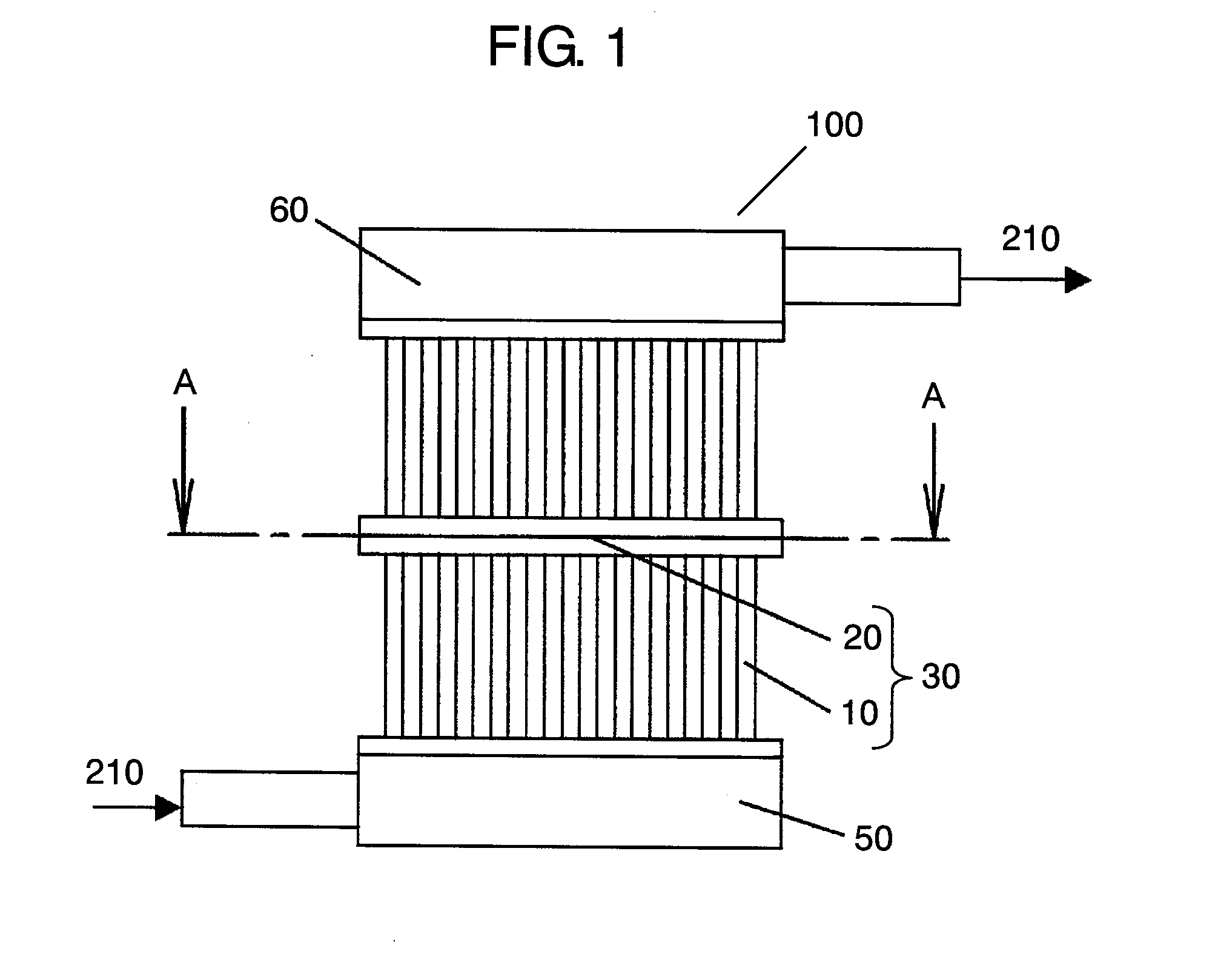
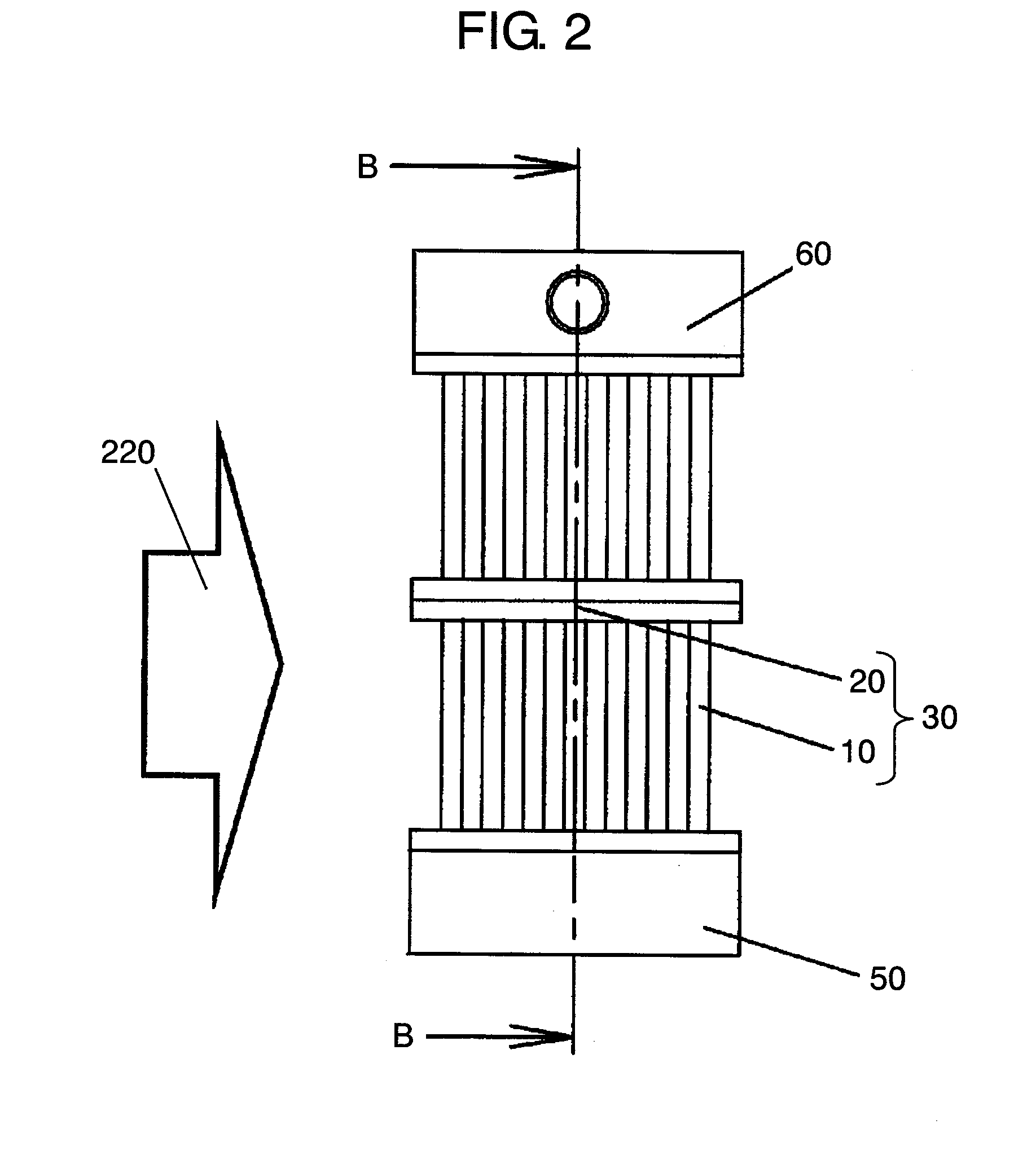
[0078]FIG. 1 shows a front view of a heat exchanger in accordance with the first embodiment of the present invention. FIG. 2 shows a lateral view of the heat exchanger, and FIG. 3 shows a sectional view cut along line A-A in FIG. 1, and FIG. 4 shows a sectional view cut along line B-B in FIG. 2.

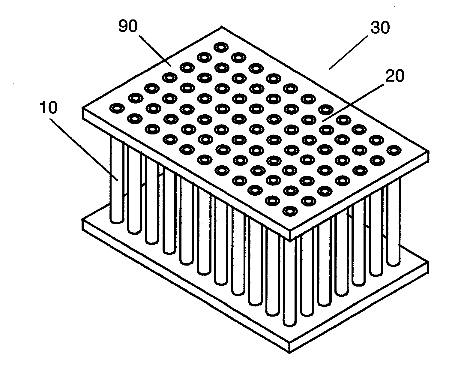
[0079]As shown in FIG. 1-FIG. 4, heat exchanger 100 in accordance with the first embodiment includes tube-group blocks 30 formed of tubes 10 and substrates 20. Two tube-group blocks 30 are layered by connecting tubes 10 along the tube axis at peripheries 90 of substrates 20. Inlet header 50 and outlet header 60 are placed on the lower end and the upper end of layered blocks 30.

[0080]Each one of tubes 10 forms a cylindrical tube and includes one flow path through which inner fluid runs. Tube 10 is not necessarily a cylindrical one, e.g. it can be a tube of which cross section shapes like a rectangle, polygon or ellipse. Peripheries 90 of substrates 20 are connected to each other directly witho...

exemplary embodiment 2

[0093]FIG. 8 shows a front view of a heat exchanger in accordance with the second embodiment of the present invention. FIG. 9 shows a lateral view of the heat exchanger, FIG. 10 shows a sectional view cut along line C-C in FIG. 8, and FIG. 11 shows a sectional view cut along line D-D in FIG. 9.

[0094]In FIG. 8-FIG. 11, heat exchanger 200 includes tube-group blocks 130 formed of tubes 110 and substrates 120. Peripheries 190 of substrates 120 are bonded together so that blocks 130 are coupled to each other in two layers along the axial direction of tubes 130, and inlet header 150 and outlet header 160 are placed on the lower and the upper ends of the two layers respectively.

[0095]In this second embodiment, each one of tubes 110 has a flat sectional view and includes a plurality of flow paths 115 arranged along the long side of the flat shape. Tubes 110 are arranged on substrates 120 such that they are in parallel with the long side respectively at given intervals. Peripheries 190 of su...

exemplary embodiment 3

[0105]FIG. 15 shows a front view of a heat exchanger in accordance with the third embodiment of the present invention. FIG. 16 shows a lateral view of the heat exchanger, FIG. 17 shows a sectional view cut along line A-A in FIG. 16, and FIG. 18 shows a sectional view cut along line B-B in FIG. 16. Elements similar to those used in the first embodiment have the same reference marks, and the descriptions thereof can be simplified.

[0106]In FIG. 15-FIG. 18, heat exchanger 300 includes tube-group blocks 40 formed of tubes 10, substrates 20 and spacers 80. Tube-group blocks 40 are placed one upon another in three layers along the flowing direction of the inner fluid running through tubes 10, and inlet header 50 and outlet header 60 are placed on the lower end and the upper end respectively of the three layers. Spacers 80 are projected stepwise from the peripheries of substrates 20 by a given height and a given width.

[0107]Each one of tubes 10 forms a cylindrical tube and includes one flow...


PUM

PropertyMeasurementUnit
outer diameteraaaaaaaaaa
heightaaaaaaaaaa

Abstract

A heat exchanger is formed by connecting tube-group blocks along a tube axis, where each one of tube-group blocks includes a plurality of substrates having a large number of through holes, which communicate with insides of a plurality of tubes placed between the substrates. A length of the tubes can be shortened so that the tube-group block can be formed within a predetermined size. The substrates and the tubes can be formed by injection molding or die-casting simultaneously with ease, so that the manufacturing steps of inserting the tubes and bonding the substrates can be eliminated. The heat exchanger can be available at a lower cost while it maintains excellent heat exchanging performance.

Description

TECHNICAL FIELD[0001]The present invention relates to a heat exchanger to be used in a cooling system, heat dissipation system, and heating system. More particularly, it relates to a heat exchanger between liquid and gas, which exchanger is employed in a system requiring compactness such as an information-processing device. The present invention also relates to a method of producing the same heat exchanger.BACKGROUND ART[0002]A conventional heat exchanger of this kind is generally formed of tubes and fins, and this exchanger has been downsized by using tubes arranged in a higher density, i.e. tubes having a smaller diameter are arranged at smaller intervals. Unexamined Japanese Patent Publication No. 2001-116481 (cited reference 1) discloses an example of the downsized heat exchanger that employs tubes measuring as small as approx. 0.5 mm in outer diameter.[0003]FIG. 29 shows a front view of the conventional heat exchanger disclosed in cited reference 1.[0004]As shown in FIG. 29, th...

Claims


Application Information

Patent Timeline
Patent Type & Authority Applications(United States)
IPC IPC(8): F28F9/02B23P15/26
CPCF28D1/05333Y10T29/49377F28F9/262F28D1/05366F28D1/053
Inventor TANIGUCHI, MITSUNORIKIDO, OSAOKINOSHITA, KIYOSHIOKUTANI, TAKASHI
Owner PANASONIC CORP
Why Eureka
Try Eureka