Ejector and negative pressure supply apparatus for brake booster using the ejector

a negative pressure supply and ejector technology, which is applied in the direction of brake systems, vehicle components, transportation and packaging, etc., can solve the problems of no clear specifications or data, and the negative pressure supply apparatus for the brake booster cannot generate a predetermined large negative pressure, and achieve the effect of short operating tim

Inactive Publication Date: 2008-05-29
AISAN IND CO LTD
View PDF0 Cites 44 Cited by
  • Summary
  • Abstract
  • Description
  • Claims
  • Application Information

AI Technical Summary

Benefits of technology

[0008]The present invention has an object to provide an ejector capable of generating a predetermined large (high) negative pressure in a short operating time and a negative pressure supply apparatus for brake booster using the ejector.

Problems solved by technology

However, the aforementioned ejector and negative pressure supply apparatus for brake booster have no clear specifications or data for allowing a predetermined large (high) negative pressure to be generated in a short operating time (with high response).
Thus, the above ejector and the negative pressure supply apparatus for brake booster could not generate a predetermined large negative pressure in a short operating time.

Method used


Image

  • Ejector and negative pressure supply apparatus for brake booster using the ejector
  • Ejector and negative pressure supply apparatus for brake booster using the ejector
  • Ejector and negative pressure supply apparatus for brake booster using the ejector

Examples


Embodiment Construction

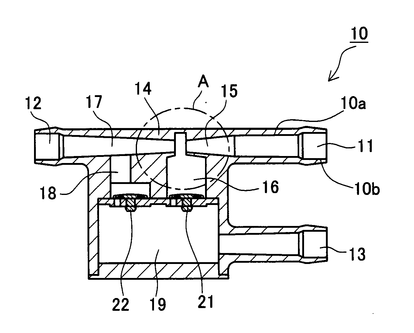
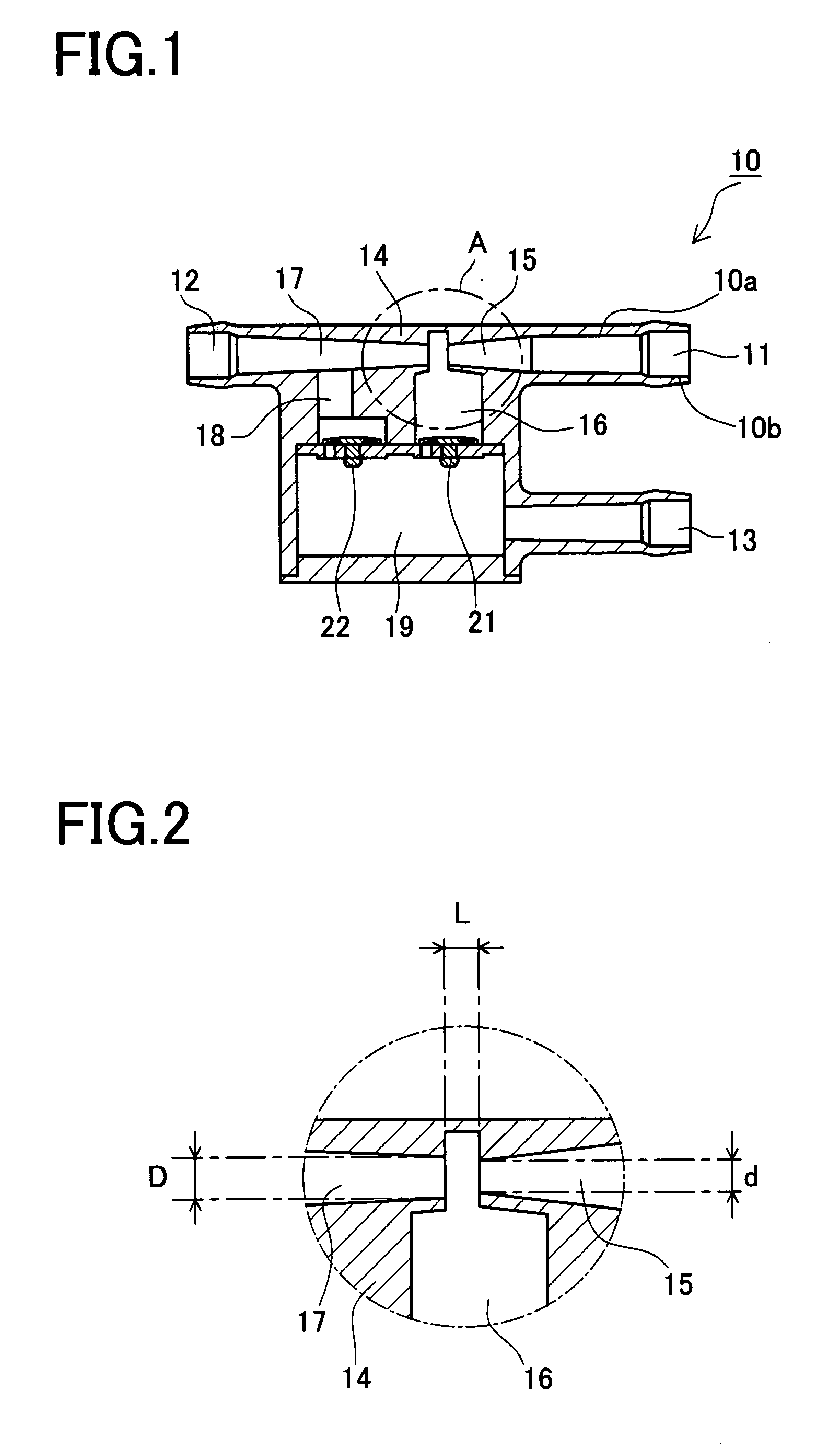
[0030]A detailed description of a preferred embodiment of an ejector embodying the present invention will now be given referring to the accompanying drawings. This ejector of the present embodiment will be explained referring to FIGS. 1 and 2. FIG. 1 is a sectional view showing a schematic configuration of the ejector of the present embodiment. FIG. 2 is an enlarged view of a part A circled with a dashed line in FIG. 1.

[0031]Referring to FIG. 1, an ejector 10 includes a housing 14 formed with an inlet port 11 through which a fluid will flow in the ejector 10, an outlet port 12 through which the fluid will flow out of the ejector 10, and a joint port 13 which will be coupled to an object to be supplied with a negative pressure. The housing 14 is further formed with a nozzle 15, a decompression chamber 16, a diffuser 17, a communication passage 18, and a suction chamber 19 in addition to the inlet port 11, the outlet port 12, and the joint port 13.

[0032]The nozzle 15 is configured to ...


PUM


Abstract

An ejector including a nozzle communicating with a fluid inlet, a diffuser communicating with a fluid outlet, and a decompression chamber placed between the nozzle and he diffuser. The ejector is arranged to generate a negative pressure in the decompression chamber by a fluid ejected from the nozzle. A target negative pressure P in the decompression chamber is set in a range of “40 kPa<P≦50 kPa”. A SD/Sd ratio between a sectional area SD of an inlet of the diffuser and a sectional area Sd of an outlet of the nozzle is determined to meet a relation:
“1.20≦SD/Sd≦4.08−0.047P”.

Description

BACKGROUND OF THE INVENTION[0001]1. Field of the Invention[0002]The present invention relates to an ejector for generating a negative pressure and a negative pressure supply apparatus using the ejector. More particularly, the present invention relates to an ejector arranged to rapidly generate a target negative pressure and a negative pressure supply apparatus for brake booster, using the ejector.[0003]2. Description of Related Art[0004]Heretofore, an ejector has been utilized for generating a negative pressure. This ejector is arranged to generate a negative pressure by air ejected from a nozzle. To improve performance of the ejector, various techniques have been proposed. One of the techniques is for example to design a throat with a diameter larger at a predetermined ratio than a diameter of the nozzle and set a predetermined distance between the nozzle and the throat, thereby improving the ejector performance (Japanese Unexamined Utility Model Publication No. 62-112000(1987).[00...

Claims


Application Information

Patent Timeline
Patent Type & Authority Applications(United States)
IPC IPC(8): B60T11/00
CPCB60T17/02B60T13/52
Inventor KAWAMORI, YUTAKANISHITANI, TSUTOMUITO, YOSHIKITSUKIJI, KIYOSHI
Owner AISAN IND CO LTD
Why Eureka
Try Eureka