Self-calibration circuit for capacitance mismatch

a capacitance mismatch and self-calibration technology, applied in the field of self-calibration circuit for capacitance mismatch, can solve the problems of circuit performance restriction, circuit cannot achieve the level of original design, cost additional expenditure and a great deal of time, etc., to achieve simple design, simplify circuit design, and facilitate integration

Inactive Publication Date: 2007-01-30
PROLIFIC TECH INC
View PDF10 Cites 33 Cited by
  • Summary
  • Abstract
  • Description
  • Claims
  • Application Information

AI Technical Summary

Benefits of technology

[0011]Accordingly, an object of the present invention is to provide a self-calibration circuit for capacitance mismatch, wherein the calibration for capacitance mismatch is integrated into the IC, thus achieving the effect of self-calibration. The advantages of the self-calibration circuit include: simplification of the circuit design, simple design and easy integration, a relatively short clock operation time, a small circuit hardware area, lower manufacturing cost, suitability for various ICs requiring a high degree of capacitance matching, and no additional power consumption when the original system is under normal operation.

Problems solved by technology

In ICs, such as switch-capacitor circuits and digital-to-analog converters (DACs), etc., the performance of the circuits might be restricted due to capacitance mismatch resulting from deviation in the manufacturing process, such that the circuit cannot achieve the level of the original design.
However, regardless whether laser trim or FIB, additional manual resources are required to measure and calibrate the chipped ICs, and it will cost additional expenditure and a great deal of time, thus the manufacturing cost will be increased.
First, an S / H and shift circuit 102 comprising an S / H circuit and a real-time switching circuit is required for the original design, which increases the complexity of the circuit design.
Second, a plurality of analog voltages corresponding to digital codes should be generated by the DAC 104 for comparison, and the voltage source and the precision of this design are problematic. Moreover, the circuit design is very complicated.
Third, repeated modification steps for each of the digital codes are needed in this method, thus the clock operation time required is quite long, and the hardware area of the digital circuit is very large.

Method used


Image

  • Self-calibration circuit for capacitance mismatch
  • Self-calibration circuit for capacitance mismatch
  • Self-calibration circuit for capacitance mismatch

Examples


Embodiment Construction

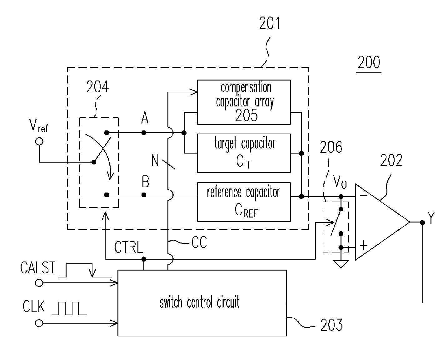
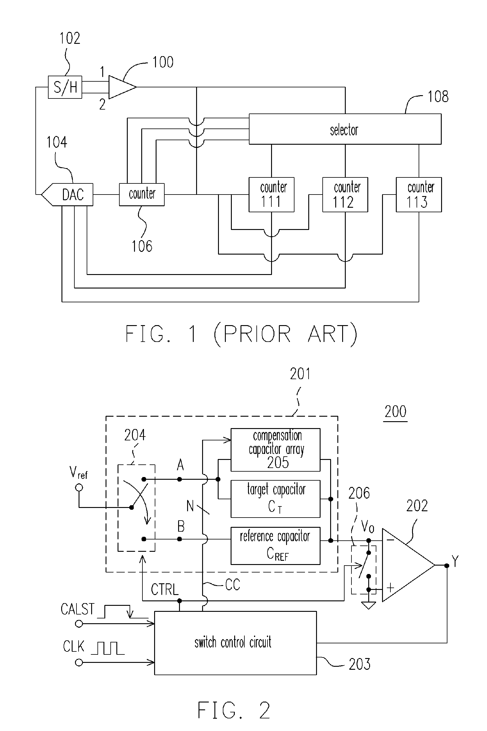
[0028]FIG. 2 is an architectural view of a self-calibration circuit for capacitance mismatch 200 according to an embodiment of the present invention. The construction architecture of the self-calibration circuit 200 is described first below, and then the operating process is described in detail.

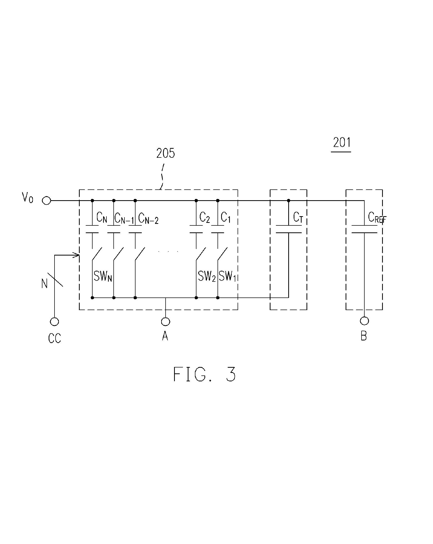
[0029]The self-calibration circuit 200 mainly includes a sample-and-hold (S / H) circuit 201, a comparator 202, and a switch control circuit 203. The S / H circuit 201 includes a switch 204, a compensation capacitor array 205, a target capacitor CT, and a reference capacitor CREF, and provides an output voltage Vo.

[0030]The switch 204 is controlled by a switch control signal CTRL. If the switch control signal CTRL is at a first state (logic 1 in this embodiment), the switch 204 connects the reference voltage Vref and the connection point B; if the switch control signal CTRL is at a second state (logic 0 in this embodiment), the switch 204 connects the reference voltage Vref and the connection poi...


PUM


Abstract

A self-calibration circuit for capacitance mismatch is provided. The circuit comprises a sample-and-hold (S/H) circuit, a comparator, and a switch control circuit. The S/H circuit comprises a compensation capacitor array, a target capacitor, and a reference capacitor. The S/H circuit provides an output voltage, wherein the output voltage is an operation result based on the capacitance of the target capacitor and the reference capacitor, and the equivalent capacitance of the compensation capacitor array. The comparator provides a comparison signal according to whether the output voltage of the S/H circuit is positive or negative. The switch control circuit controls the equivalent capacitance of the array according to the comparison signal such that the result of the target capacitance added to the equivalent capacitance of the array gradually approximates the reference capacitance with each cycle of a clock signal.

Description

CROSS-REFERENCE TO RELATED APPLICATION[0001]This application claims the priority benefit of Taiwan application serial no. 94139397, filed on Nov. 10, 2005. All disclosure of the Taiwan application is incorporated herein by reference.BACKGROUND OF THE INVENTION[0002]1. Field of Invention[0003]The present invention relates to a self-calibration circuit for capacitance mismatch, and more particularly to an approximation self-calibration circuit for capacitance mismatch.[0004]2. Description of Related Art[0005]In integrated circuits (IC), capacitance match is always one of the important design considerations. In ICs, such as switch-capacitor circuits and digital-to-analog converters (DACs), etc., the performance of the circuits might be restricted due to capacitance mismatch resulting from deviation in the manufacturing process, such that the circuit cannot achieve the level of the original design. Therefore, with IC design, how to compensate the capacitance mismatch caused by deviation...

Claims


Application Information

Patent Timeline
Patent Type & Authority Patents(United States)
IPC IPC(8): H03M1/12
CPCH03M1/1009H03M1/0678H03M1/804H03M1/468
Inventor CHEN, HSUAN-FAN
Owner PROLIFIC TECH INC
Why Eureka
Try Eureka