

Multiband antenna
- Summary
- Abstract
- Description
- Claims
- Application Information
AI Technical Summary
Benefits of technology
Problems solved by technology
Method used
Image

Examples
first embodiment
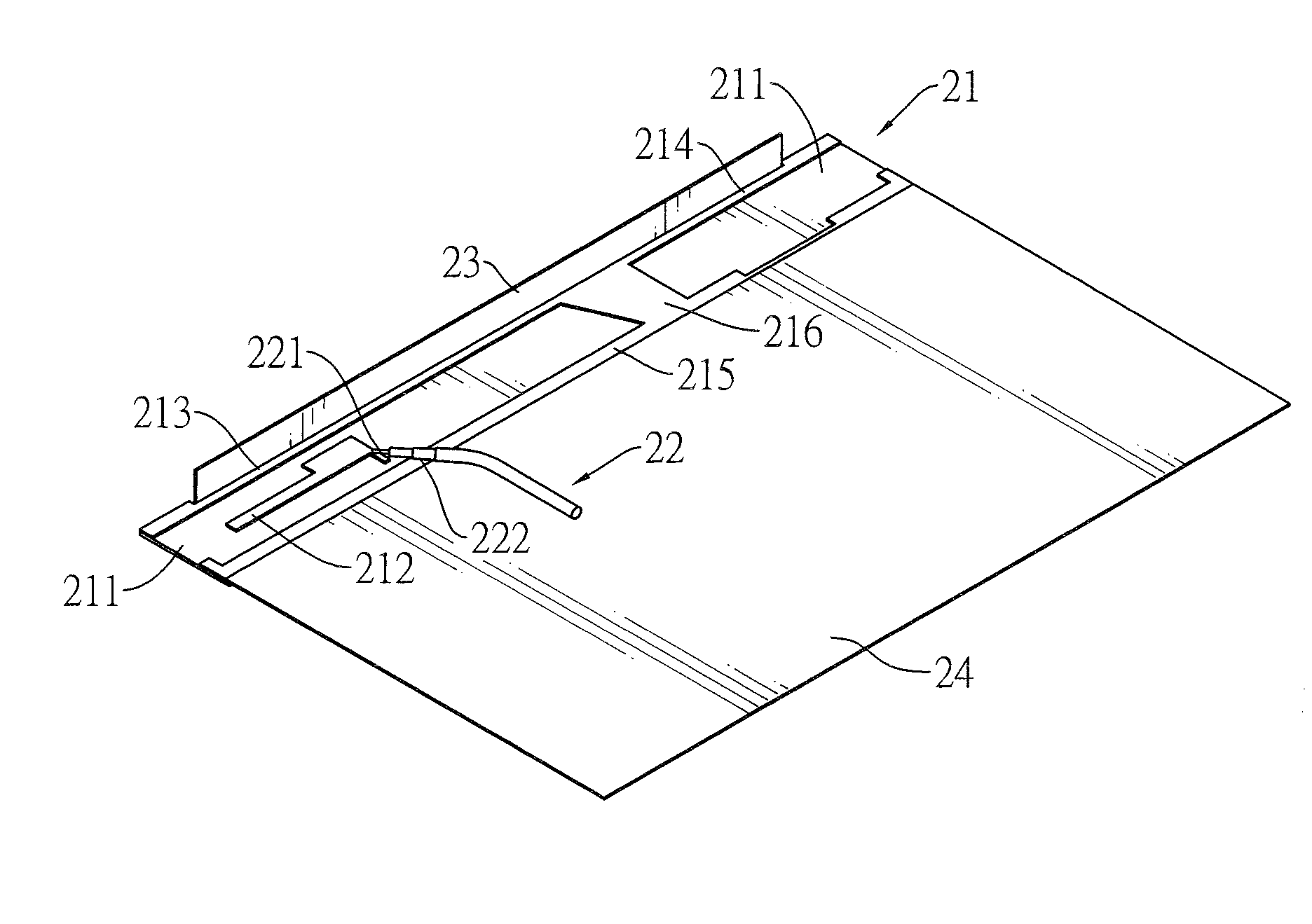
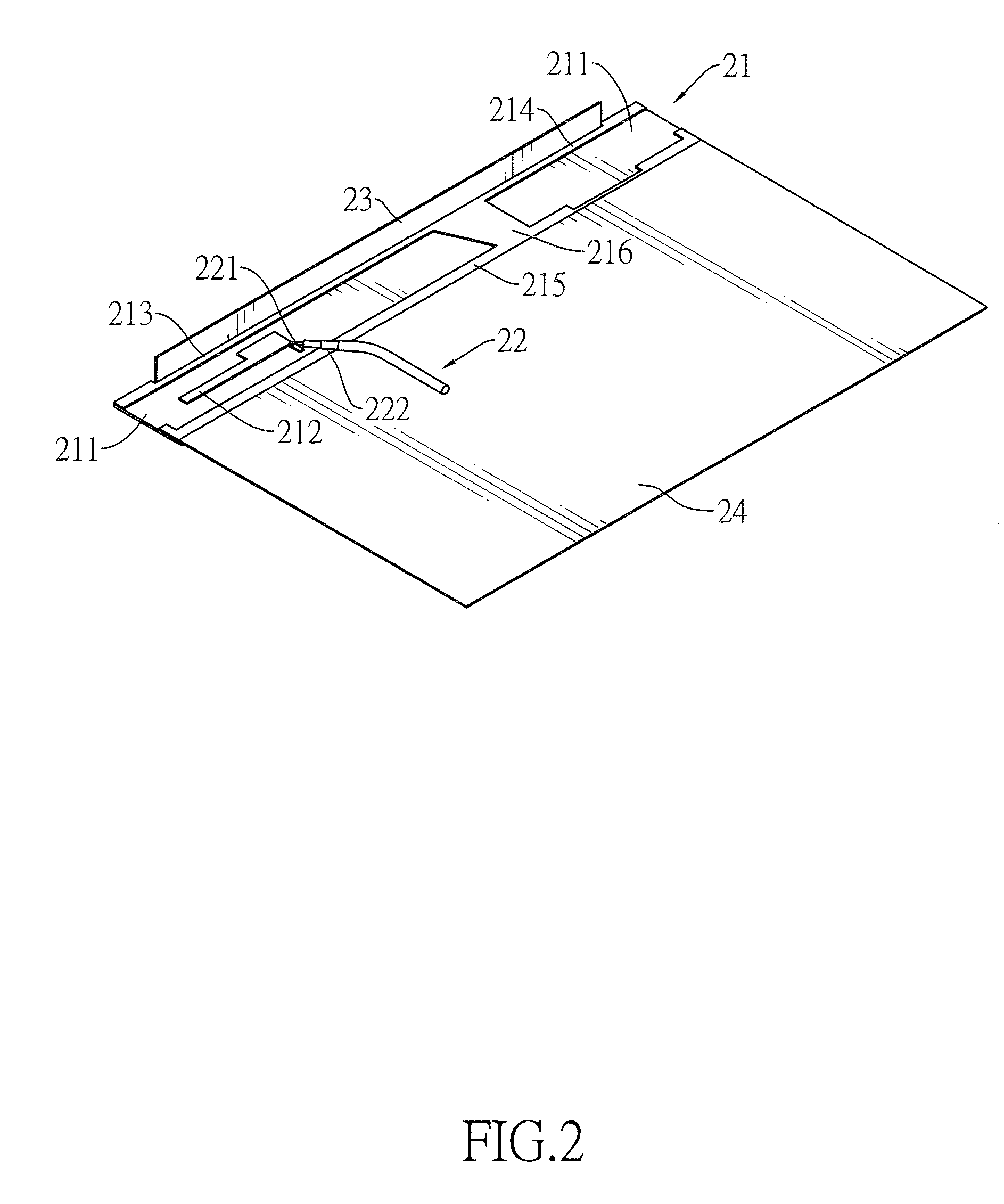
[0020]With reference to FIG. 2, a multiband antenna comprises a radiator 21, a feed cable 22, a first extension conductor 23, and a second extension conductor 24.
[0021]The radiator 21 includes a microwave substrate 211, a coupling conductor 212, a first conductor 213, a second conductor 214, a third conductor 215 and a connecting conductor 216. The coupling conductor 212 is disposed on the microwave substrate 211. The first conductor 213 is disposed on the microwave conductor 211 and is adjacent to the coupling conductor 212 to form a coupling structure that has a coupling clearance as small as 3 mm, thereby feeding electrical signals into the antenna. The second conductor 214 is disposed on the microwave substrate 211, with one end connected with the first conductor 213 and the other end extending away from the first conductor 213. The third conductor 215 is disposed on the microwave substrate 211 in parallel to the first conductor 213. The connecting conductor 216 is disposed on t...
second embodiment
[0026]With reference to FIG. 4, the multiband antenna comprises a radiator 41, a feed cable 42, a first extension conductor 43, and a second extension conductor 44.
[0027]The radiator 41 includes a microwave substrate 411, a coupling conductor 412, a first conductor 413, a second conductor 414, a third conductor and a connecting conductor 416.
[0028]The coupling conductor 412 is disposed on the microwave substrate 411. The first conductor 413 is disposed on the microwave conductor 411 and is adjacent to the coupling conductor 412 to form a coupling structure that has a coupling clearance less than 3 mm, thereby feeding electrical signals into the antenna. The second conductor 414 is disposed on the microwave substrate 411, with one end connected with the first conductor 413 and the other end extending away from the first conductor 413. The third conductor 415 is disposed on the microwave substrate 411 and extends in parallel with the first conductor 413. The connecting conductor 416 i...
third embodiment
[0031]With reference to FIG. 5, the multiband antenna comprises a radiator 51, a feed cable 52, a first extension conductor 53, and a second extension conductor 54.
[0032]The radiator 51 includes a microwave substrate 511, a coupling conductor 512, a first conductor 513, a second conductor 514, a third conductor 515 and a connecting conductor 516.
[0033]The coupling conductor 512 is disposed on the microwave substrate 511. The first conductor 513 is disposed on the microwave conductor 511 and is adjacent to the coupling conductor 512 to form a coupling structure that has a coupling clearance less 3 mm, thereby feeding electrical signals into the antenna. The second conductor 514 is disposed on the microwave substrate 511, with one end connected with the first conductor 513 and the other end extending away from the first conductor 513. The third conductor 515 is disposed on the surface of the microwave substrate 511 and extends in parallel to the first conductor 513. The connecting con...
PUM
 Abstract
Description
Claims
Application Information