Eureka AIR delivers breakthrough ideas for toughest innovation challenges, trusted by R&D personnel around the world.

A miniaturized omnidirectional uhf-rfid tag antenna and its preparation method

A technology of UHF-RFID and tag antenna, which is applied in chemical/electrolytic methods to remove conductive materials, antennas, resonant antennas, etc., can solve the problems of applicable scene constraints, affecting reading accuracy, etc. Gain and Omnidirectionality, Size Reduction Effects

Active Publication Date: 2022-06-07
HUNAN INSTITUTE OF ENGINEERING
View PDF7 Cites 0 Cited by
  • Summary
  • Abstract
  • Description
  • Claims
  • Application Information

AI Technical Summary

Problems solved by technology

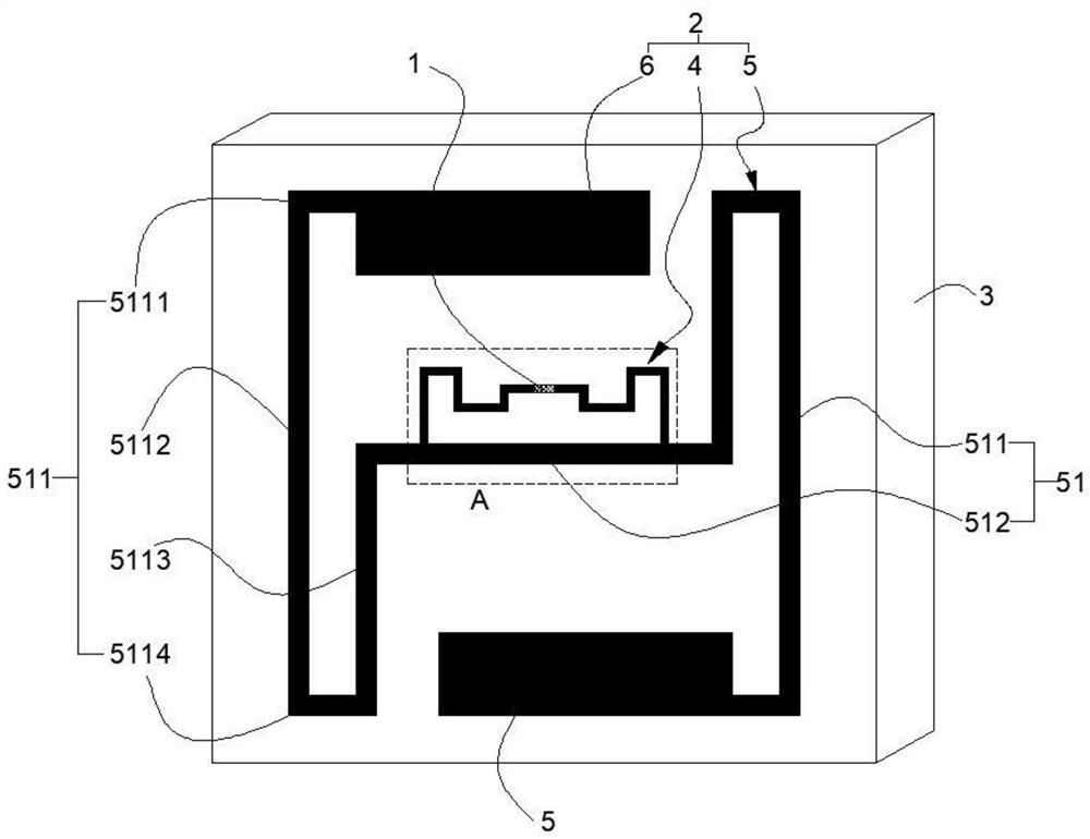
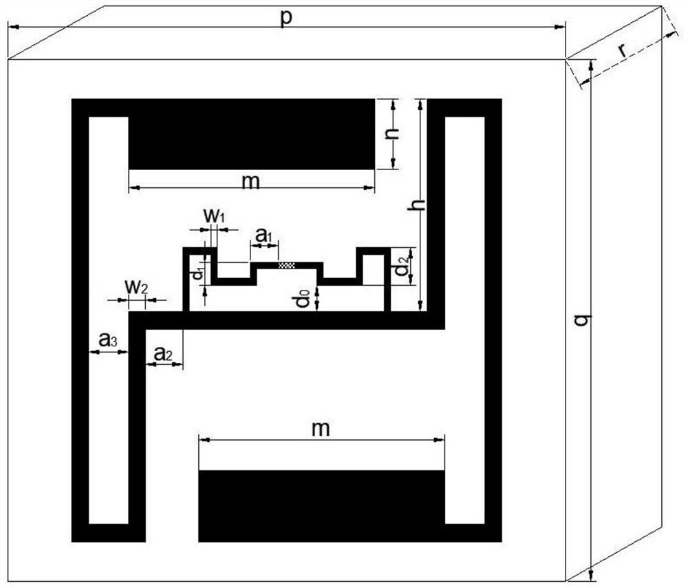
[0007] Aiming at the deficiencies in the prior art, the purpose of the present invention is to provide a miniaturized omnidirectional UHF-RFID tag antenna and its preparation method, by synchronously improving the structure and preparation process of the antenna, it not only meets the miniaturization requirements of the electronic tag , it can also solve the problem that its applicable scenarios are restricted due to the narrow bandwidth of the antenna and affect the reading accuracy; on the basis of realizing miniaturization, satisfying a large impedance bandwidth and reading distance, the gain and omnidirectionality are guaranteed, and it is easy to Manufacturing and Industrialization

Method used


Image

  • A miniaturized omnidirectional uhf-rfid tag antenna and its preparation method
  • A miniaturized omnidirectional uhf-rfid tag antenna and its preparation method
  • A miniaturized omnidirectional uhf-rfid tag antenna and its preparation method

Examples


Embodiment 2

[0074] This embodiment provides a method for preparing the aforementioned miniaturized omnidirectional UHF-RFID tag antenna, which includes the following steps:

[0075] (1) Prepare the dielectric substrate 3, the antenna chip 1, and the conductive metal paste respectively;

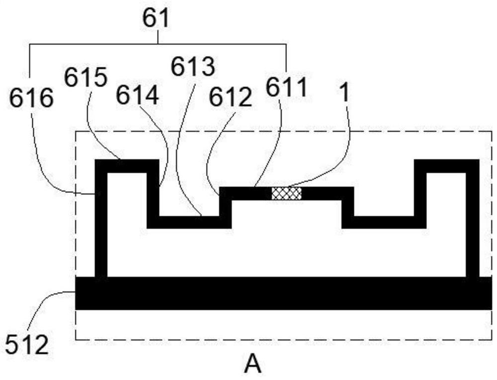
[0076] (2) Calculate the position of the closed inner loop 61 in the horizontal direction of the middle horizontal bending section 512 according to the required operating frequency;

[0077] (3) The conductive metal paste is printed on the medium at one time according to the shape, position and size of the tapered Meander T-match impedance matching network 4, the antenna arm 5 and the radiation patch Tip-Loading6 in the radiation antenna 2 by the printing method. The outer surface of the substrate 3 is dried and shaped;

[0078] (4) Solder the antenna chip 1 on the conical Meander T-match impedance matching network 4 to obtain a miniaturized omnidirectional UHF-RFID tag antenna.

[0079] The miniaturize...

Embodiment 3

[0081] This embodiment provides the aforementioned preparation method of the miniaturized omnidirectional UHF-RFID tag antenna, which includes the following steps:

[0082] (1) Prepare the dielectric substrate 3, the antenna chip 1, and the conductive metal foil respectively;

[0083] (2) Calculate the position of the closed inner loop 61 in the horizontal direction of the middle horizontal bending section 512 according to the required operating frequency;

[0084] (3) Lay the conductive metal foil on the outer surface of the dielectric substrate 3 by the etching method, according to the shape, position and size, one-time printing paint on the metal foil on the outer surface of the dielectric substrate 3, and then corroding the foil, degreasing, drying, and spraying insulating paint;

[0085] (4) Solder the antenna chip 1 on the conical Meander T-match impedance matching network 4 to obtain a miniaturized omnidirectional UHF-RFID tag antenna. The antenna chip 1 is soldered i...


PUM


Abstract

The invention discloses a miniaturized omnidirectional UHF-RFID tag antenna, which includes an antenna chip, a radiation antenna and a dielectric substrate; the radiation antenna includes an antenna arm, an impedance matching network and a radiation patch; the antenna arm is an open type The outer loop; the radiation patch is center-symmetrically arranged with the center of the dielectric substrate as the reference point; the overall outline of the impedance matching network is "E"; the antenna chip is electrically connected to the tapered impedance matching network to form a closed inner loop ; The open outer loop loop forms a single-sided bent dipole antenna; the two radiating patches form a rectangular patch antenna for capacitive top loading; the dielectric substrate, closed inner loop loop, bent The folded dipole antenna and the rectangular patch antenna cooperate with each other to improve the working bandwidth, gain and antenna omnidirectionality of the antenna while reducing the size of the radiation antenna and shortening the length of the antenna. The invention also discloses the preparation method of the antenna.

Description

technical field [0001] The invention relates to the technical field of radio frequency identification and the Internet of Things, in particular to a miniaturized omnidirectional UHF-RFID tag antenna and a preparation method thereof. Background technique [0002] RFID is a non-contact automatic identification technology realized by radio frequency communication. It includes two main parts: an electronic tag (tag) and a reader (reader). Transmission to complete the automatic identification process at a certain distance. The RFID tag antenna generally refers to the transponder antenna of the RFID electronic tag, which is a kind of communication induction antenna. Due to different materials and manufacturing processes, RFID tag antennas are divided into metal etched antennas, printed antennas, and copper-plated antennas. As an important part of the RFID system, the RFID tag antenna plays a key role in the realization of data communication, so the antenna design is the key to t...

Claims


Application Information

Patent Timeline
Patent Type & Authority Patents(China)
IPC IPC(8): H01Q1/22H01Q1/00H01Q1/38H01Q1/50H01Q9/04H05K3/06H05K3/12H05K3/22
CPCH01Q1/2225H01Q1/002H01Q1/38H01Q1/50H01Q9/0407H05K3/12H05K3/1283H05K3/06H05K3/227
Inventor 邓永和刘晓毅贺君颜铄清
Owner HUNAN INSTITUTE OF ENGINEERING
Why Eureka
Eureka Blog
Learn More