
Planar dipole binary parasitic array antenna

An array antenna and dipole technology, which is applied in the field of planar dipole binary parasitic array antennas, can solve the problems of complex antenna feeding network design and structure, and achieve the effects of improving impedance matching degree, large antenna gain and simple structure.

Pending Publication Date: 2021-06-04
GUILIN UNIV OF ELECTRONIC TECH +1
View PDF0 Cites 0 Cited by
  • Summary
  • Abstract
  • Description
  • Claims
  • Application Information

AI Technical Summary

Problems solved by technology

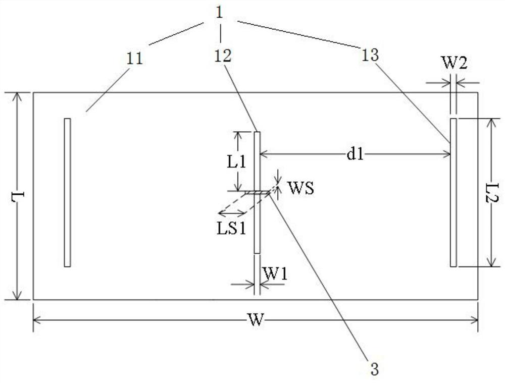
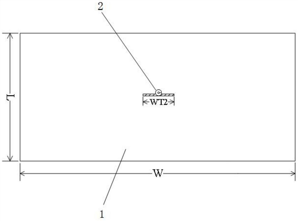
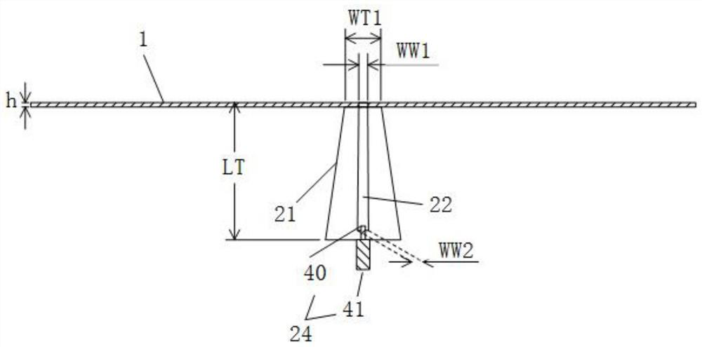
[0003] The purpose of the present invention is to provide a planar dipole binary parasitic array antenna, which aims to solve the technical problem of complex design structure of the dipole array antenna feeding network in the prior art

Method used


Image

  • Planar dipole binary parasitic array antenna
  • Planar dipole binary parasitic array antenna
  • Planar dipole binary parasitic array antenna

Examples


Embodiment Construction

[0026] Embodiments of the present invention are described in detail below, examples of which are shown in the drawings, wherein the same or similar reference numerals designate the same or similar elements or elements having the same or similar functions throughout. The embodiments described below by referring to the figures are exemplary and are intended to explain the present invention and should not be construed as limiting the present invention.

[0027] In describing the present invention, it should be understood that the terms "length", "width", "upper", "lower", "front", "rear", "left", "right", "vertical", The orientation or positional relationship indicated by "horizontal", "top", "bottom", "inner", "outer", etc. are based on the orientation or positional relationship shown in the drawings, and are only for the convenience of describing the present invention and simplifying the description, rather than Nothing indicating or implying that a referenced device or element...


PUM


Abstract

The invention discloses a planar dipole binary parasitic array antenna, which is characterized in that parasitic metal units are additionally arranged on two sides of a planar dipole antenna, and the lengths and the positions of the metal units are properly adjusted, so that the antenna gain can be greatly increased, and the problems of large antenna size and complex antenna structure are solved. Besides, the planar dipole binary parasitic array is only provided with one feed port, the impedance matching degree of the antenna can be improved by adjusting the length and the position of the parasitic strip metal units, the gain of the antenna is improved, and the planar dipole binary parasitic array is simple in structure, easy to process, low in cost, high in precision and suitable for mass production, and can be produced by using a PCB. The technical problem that a dipole array antenna feed network in the prior art is complex in design structure is solved.

Description

technical field [0001] The invention relates to the technical field of antennas, in particular to a planar dipole binary parasitic array antenna. Background technique [0002] Dipole antenna is the most widely used type of antenna so far. It can be applied in the field of wireless communication, radar and space detection, and can usually be designed to work in multiple frequency bands. This type of antenna has a simple structure, is easy to process and manufacture, and is convenient for feeding. The most common type of dipole antenna is the half-wave dipole antenna, also known as the half-wave element antenna, which is the most basic wire antenna. The dipole antenna in the form of microstrip is a metal strip of a certain shape that is etched on one side of a thin dielectric plate by photolithography and other methods, and is fed by direct or indirect coupling with a microstrip line. At the same time, there are also dipole array antennas, and such antennas generally need to...

Claims


Application Information

Patent Timeline
Patent Type & Authority Applications(China)
IPC IPC(8): H01Q1/38H01Q21/00H01Q13/10
CPCH01Q1/38H01Q13/10H01Q21/00
Inventor 王宜颖孙佳文王波于新华莫锦军王俊余烈田
Owner GUILIN UNIV OF ELECTRONIC TECH
Learn More