Structure of light guide board

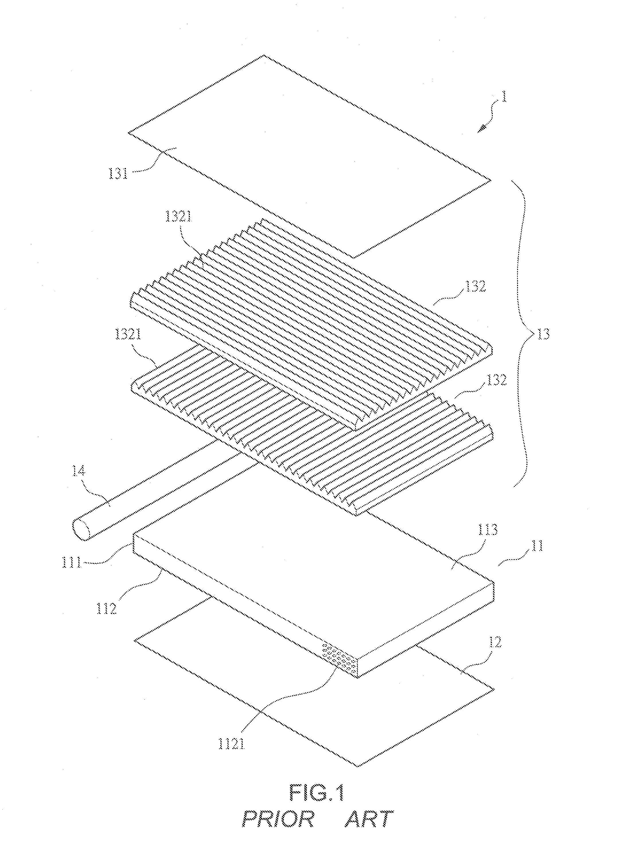
a light guide board and structure technology, applied in the direction of planar/plate-like light guides, lighting and heating apparatus, instruments, etc., can solve the problems of high price of prism films b>132/b>, and achieve enhanced roughness, enhanced surface roughness, and eliminated brightness zones

Inactive Publication Date: 2008-05-29
RADIANT OPTO ELECTRONICS
View PDF5 Cites 20 Cited by
  • Summary
  • Abstract
  • Description
  • Claims
  • Application Information

AI Technical Summary

Benefits of technology

[0015]The primary purpose of the present invention is to provide a light guide board, which allows light that is received from a light source through a light incidence surface of the light guide board to be uniformly diffused and transmitted into the light guide board so as to eliminate brightness zone occurring in a light emitting surface due to insufficient diffusion of light in the light incidence surface.
[0016]Thus, an objective of the present invention is to provide a light guide board comprising light guide board comprising a light incidence surface, which is frosted and comprises a roughness-enhanced zone at a location corresponding to a light source, the roughness-enhanced zone having enhanced surface roughness as compared to a non-roughness-enhanced zone so that light from the light source is subject to diffusion by the frosted face of the light incidence surface and light that is radiated by the light source to the light incidence surface can be further diffused by the roughness-enhanced zone whereby the light incidence surface effects the optimum diffusion on the light from the light source and thus eliminating brightness zones occurring in the portions of the light emitting surface close to the light incidence surface due to insufficient diffusion of light by the light incidence surface.
[0017]Another objective of the present invention is to provide a light guide board having a light emitting surface, which forms micro-structures on portions thereof adjacent to a light incidence surface an two opposite end surfaces; whereby the portions of the light emitting surface are of magnitude enhanced roughness as compared to portions of the light emitting surface that are not provided with micro-structures. Thus, light transmitting through the light emitting surface can be of further diffusion to provide the output of light of the light guide board with uniformity.
[0018]A further objective of the present invention is to provide a light guide board having a light incidence surface that is inclined and comprises a roughness-enhanced zone that is inclined with the light incidence surface so as to enhance diffusion of light from a light source and to significantly improve refraction angle of the light entering the light guide board thereby preventing brightness zones from occurring at portions of the light emitting surface close to the light incidence surface.
[0019]A further objective of the present invention is to provide a light guide board having a reflection surface, which forms a plurality of prisms, which have a starting end connected with a light incidence surface and a terminating end connected with a surface opposite to the light incidence surface and which has a height increased from the starting end to the terminating end, whereby the variation of height of the prisms causes change of the prism surface of the prisms from minimum to maximum so that the light transmitting through the prism is subject to regulation by the variable area of the prism surface to provide uniform optic energy output and thus eliminating potential brightness zones of the light guide board.
[0020]A further objective of the present invention is to provide a light guide board having a reflection surface on which prisms are formed and the prisms have a starting end that is not connected with a light incidence surface and spaced from the light incidence surface by a distance so that the light entering the light guide board is not subject to immediate convergence by the prisms for coping with powerful light source.

Problems solved by technology

However, the prism films 132 are expensive parts because the prism films are of a structure that is protected by patents and can be available from a limited number of suppliers.

Method used


Image

  • Structure of light guide board
  • Structure of light guide board
  • Structure of light guide board

Examples


Embodiment Construction

[0032]The following descriptions are of exemplary embodiments only, and are not intended to limit the scope, applicability or configuration of the invention in any way. Rather, the following description provides a convenient illustration for implementing exemplary embodiments of the invention. Various changes to the described embodiments may be made in the function and arrangement of the elements described without departing from the scope of the invention as set forth in the appended claims.

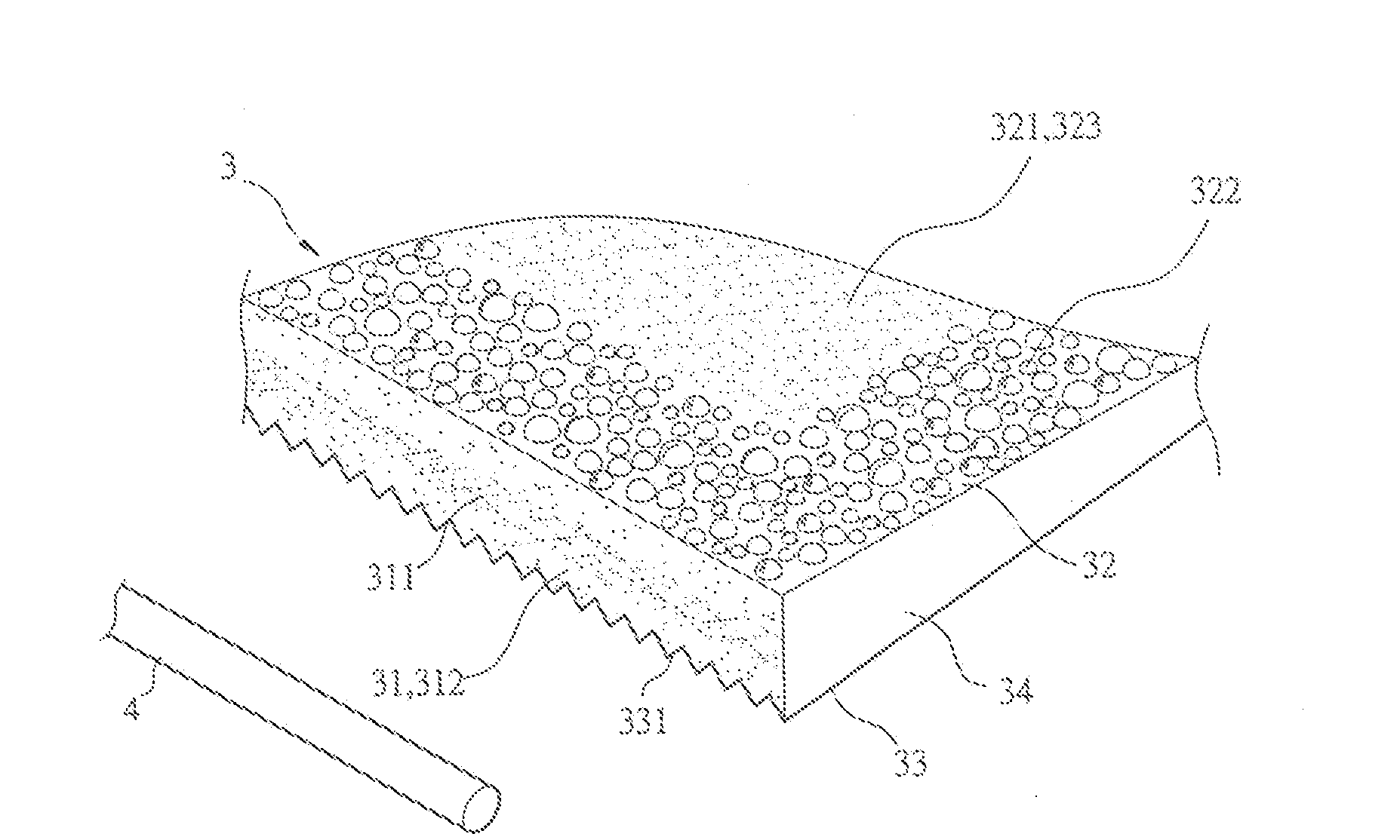
[0033]With reference to the drawings and in particular to FIG. 3, a light guide board constructed in accordance with the present invention, generally designated with reference numeral 3, is made of a material that has excellent light transmittance, such as glass and optic acrylic, and has at least a light incidence surface 31, a light emitting surface 32, and a reflection surface 33 opposite to the light emitting surface 32.

[0034]The light incidence surface 31 is a frosted surface and comprises a...


PUM


Abstract

A light guide board includes an incidence surface, an emitting surface, and a reflection surface. The incidence surface is frosted and has a roughness-enhanced zone corresponding in location to a light source. The emitting surface forms micro-structures on portions adjacent to the incidence surface and two opposite end surfaces. The portions of the emitting surface forming the micro-structures have magnitude increased roughness as compared to portions that are not provided with micro-structures so that light transmitting through the micro-structures is subject to further diffusion. The reflection surface forms a plurality of prisms extending from the incidence surface with a small (shallow) depth to an opposite surface with a large (deep) depth, with the height of the prisms increasing with the length thereof so that the prism surface of the prisms changes from minimum to maximum, which ensures uniformity of the light emitted from the light guide board.

Description

BACKGROUND OF THE INVENTION[0001](a) Technical Field of the Invention[0002]The present invention relates to a structure of a light guide board, and in particular to a wedge-shaped light guide board for use in a backlight module.[0003](b) Description of the Prior Art[0004]A backlight module is often incorporated in a liquid crystal display (LCD) for providing back lighting to the LCD. The backlight module, as a back lighting for LCD, is subject to server requirement of uniformity and brightness of light in order to provide the LCD with desired performance. As shown in FIG. 1 of the attached drawings, a conventional backlight module 1 comprises at least a light guide board 11, a reflector film 12, a number of optic films 13, and a light source 14.[0005]The light guide board 11 has at least one light incidence surface 111, a reflection surface 112, and a light emitting surface 113. The light incidence surface 111 receives light from the light source 14 to allow the light to transmit in...

Claims


Application Information

Patent Timeline
Patent Type & Authority Applications(United States)
IPC IPC(8): F21V8/00
CPCG02B6/0016G02B6/0038G02B6/0036
Inventor CHANG, CHIA-YINLIU, CHIN-FU
Owner RADIANT OPTO ELECTRONICS
Why Eureka
Try Eureka