Apparatus and method providing non-linear adaptive signal tracking

Active Publication Date: 2008-05-29
TEXAS INSTR INC
View PDF1 Cites 13 Cited by
  • Summary
  • Abstract
  • Description
  • Claims
  • Application Information

AI Technical Summary

Benefits of technology

[0008]It is, therefore, an object of the present invention to provide an apparatus and method for permitting a real time adaptive capability fo

Problems solved by technology

Such off-line software treatment contributes to slow adaptation time as compared with the period of the signal being treated, such as a radio frequency (RF) signal.
As a result, longer term variations are compensated by the distortion correcting device, but shorter term variations are not addre

Method used


Image

  • Apparatus and method providing non-linear adaptive signal tracking
  • Apparatus and method providing non-linear adaptive signal tracking
  • Apparatus and method providing non-linear adaptive signal tracking

Examples


first embodiment

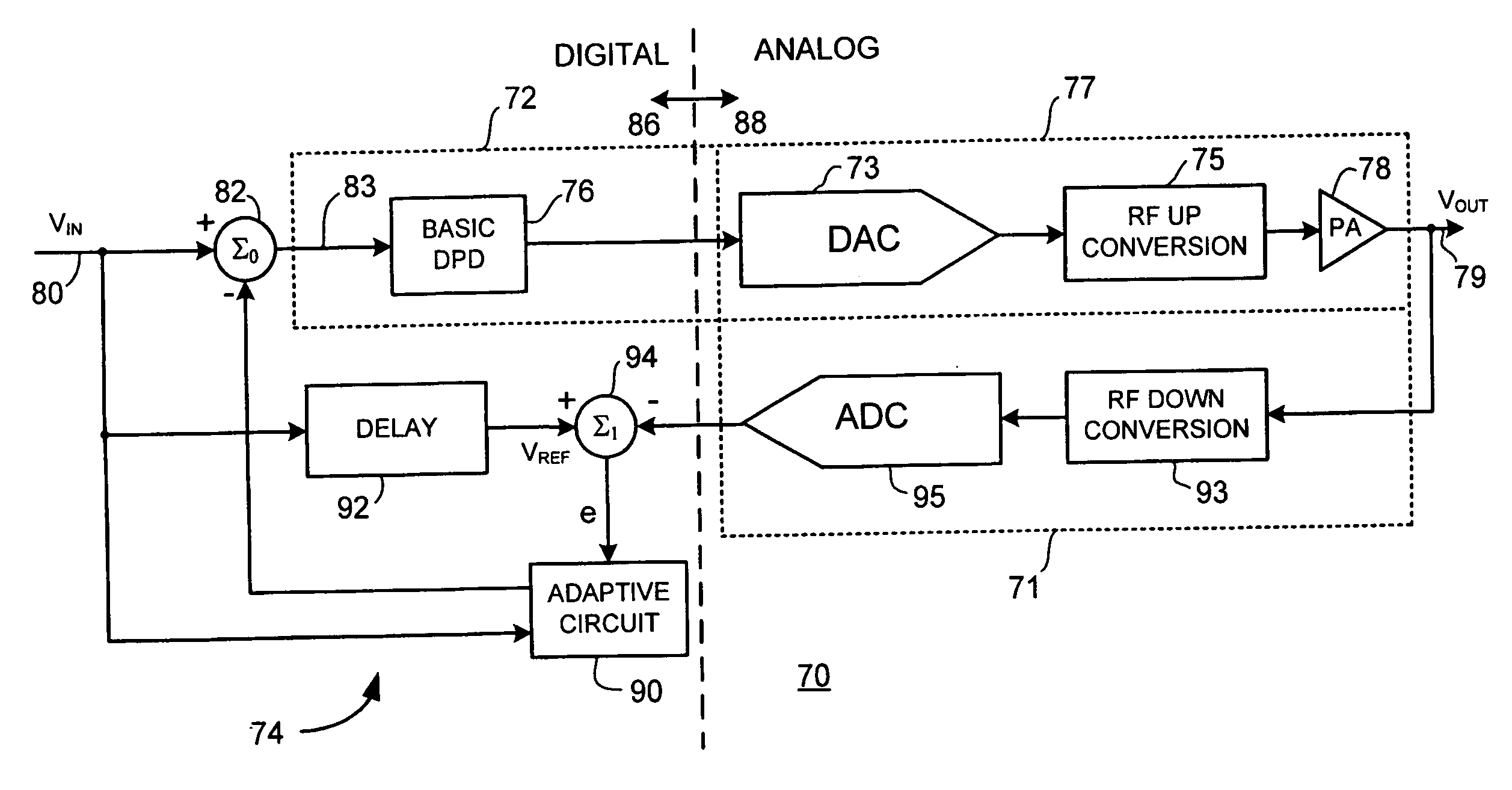
[0032]FIG. 4 is a schematic diagram of a supplemental or additional response apparatus configured according to the present invention. In FIG. 4, a distortion correcting apparatus 70 includes a distortion correcting device 72 and a supplemental correcting device 74. Distortion correcting device 72 includes a distortion correcting section 76 and a power amplifier 78. In the embodiment illustrated in FIG. 4, power amplifier 78 is included in an output section 77. Output section 77 also includes a digital-to-analog converter (DAC) 73 and an RF up-converting unit 75. Output section 77 couples distortion correcting device 72 with an output locus 79. A feedback section 71 couples output locus 79 with supplemental correcting device 74. Feedback section 71 includes an RF down-converting unit 93 and an analog-to-digital converter (ADC) 95.

[0033]Distortion correcting section 76 may be configured substantially as one of distortion correcting section 32 (FIG. 2) or distortion correcting section ...

second embodiment

[0041]FIG. 6 is a schematic diagram of a supplemental or additional response apparatus configured according to the present invention. In FIG. 6, an distortion correcting apparatus 100 is configured as a predistortion device including a distortion correcting device 102 and a supplemental correcting device 104. Distortion correcting device 102 includes a distortion correcting section 106 and a power amplifier 108. Distortion correcting section 106 operates in conjunction with software 103. Distortion correcting section 106 may be configured substantially as one of distortion correcting section 32 (FIG. 2) or distortion correcting section 52 (FIG. 3) or another distortion correcting section. Supplemental correcting device 104 includes an adaptive circuit 110, a delay unit 112 and a summing node 114.

[0042]Distortion correcting apparatus 100 receives an input signal VIN at an input locus 120. Input signal VIN is provided to a summing node 122, to a delay unit 130 and to adaptive circuit ...

third embodiment

[0051]FIG. 8 is a schematic diagram of a supplemental or additional response apparatus configured according to the present invention. In FIG. 8, a distortion correcting apparatus 150 is configured as a predistortion device including a distortion correcting device 152 and a supplemental correcting device 154. Distortion correcting device 152 includes a distortion correcting section 156 and a power amplifier 158. Distortion correcting section 152 operates in conjunction with software 153. Distortion correcting section 156 may be configured substantially as one of distortion correcting section 32 (FIG. 2) or distortion correcting section 52 (FIG. 3) or another distortion correcting section. Supplemental correcting device 154 includes an adaptive circuit 160, delay unit 162 and summing nodes 164, 165. A delay unit 163 may also be included in supplemental correcting device 154, as indicated by the dotted line rendition of delay unit 163.

[0052]Distortion or correcting apparatus 150 receiv...


PUM


Abstract

An apparatus providing additional response for a distortion correcting device that receives a first signal at a correcting input and provides a first delayed output signal at an output includes: (a) A first signal combiner coupled with an input and the correcting input. (b) A delay unit coupled with the input provides a second delayed signal to a delayed signal terminal. (c) A second signal combiner coupled with the delayed signal terminal and the output employs the output signal and the second delayed signal to present an error signal at a first error terminal. (d) An adaptive circuit coupled with the input locus, the first signal combiner and the second signal combiner employs provides a supplemental signal to the first signal combiner which employs the input signal and the supplemental signal to present the first signal to reduce the error signal.

Description

BACKGROUND OF THE INVENTION[0001]The present invention is directed to distortion correcting methods and devices, and especially to distortion correcting methods and devices configured for adaptive digital predistortion for signal correction for improved signal treatment.[0002]Prior art distortion correcting methods and devices, especially prior art distortion correcting methods and devices configured and employed for signal predistortion, compute linearization parameters for signal treatment off-line in software-executing circuitry. Such off-line software treatment contributes to slow adaptation time as compared with the period of the signal being treated, such as a radio frequency (RF) signal. As a result, longer term variations are compensated by the distortion correcting device, but shorter term variations are not addressable because of the slow adaptation time of the method and apparatus.[0003]By way of example and not by way of limitation, a distortion compensation device such ...

Claims


Application Information

Patent Timeline
IPC IPC(8): H04L27/10
CPCH03F1/3247H03F1/3258H04L25/03343H03F2201/3209H03F2201/3233H03F2200/321
Inventor COPELAND, GREGORY CLARK
Owner TEXAS INSTR INC
Why Eureka
Try Eureka