Image forming apparatus

an image forming apparatus and image technology, applied in the field of electrographic image forming apparatuses, can solve the problems of increasing and the inability to appropriately transfer the toner image onto the recording material, etc., to achieve the effect of preventing an increase in the size of the image forming apparatus

Inactive Publication Date: 2008-05-29
SHARP KK
View PDF1 Cites 6 Cited by
  • Summary
  • Abstract
  • Description
  • Claims
  • Application Information

AI Technical Summary

Benefits of technology

[0013]The present invention has been made in view of the foregoing problems, and it is an object of the present invention to more appropriately transfer a toner image onto a recording material from an image carrier in an image forming apparatus, including a conveyer belt for conveying a recording material, in which a toner image formed on an image carrier is transferred onto an intermediate transfer body and the toner image thus transferred onto the intermediate transfer body is transferred onto a recording material; and to simultaneously prevent an increase in size of the image forming apparatus.
[0015]According to the foregoing arrangement, the image forming apparatus has a charge imparting device which includes (a) an ion generating section for generating ions, (b) a first imparting section for imparting charge, with use of the ions generated by the ion generating section, to the toner image having yet to be transferred from the intermediate transfer body onto the recording material, and (c) a second imparting section for imparting charge to the recording material conveying means with use of the ions generated by the ion generating section. That is, both the toner image transferred onto the intermediate transfer body and the recording material conveying means are charged with use of the ions generated by the common ion generating section. Therefore, as compared with an arrangement in which a charge generating device for charging the toner image transferred onto an intermediate transfer body and a charge generating device for the charging recording material conveying means are separately provided, it is possible to reduce the size of the image forming apparatus and the amount of power to be consumed by the image forming apparatus. Further, the characteristics of the toner image being transferred from the intermediate transfer body onto the recording material can be stabilized by uniformly charging the toner image transferred onto the intermediate transfer body. Further, when the toner image transferred onto the intermediate transfer body and having yet to be transferred from the intermediate transfer body onto the recording material is charged so as to better cling to the intermediate transfer body, the toner image transferred on the intermediate transfer body can be prevented from dropping or scattering from the intermediate transfer body. Further, the recording material can be stably conveyed by imparting, to the recording material conveying means, charge for ridding the recording material conveying means of residual charge or charge for causing the recording material to electrostatically cling to the recoding material conveying means.

Problems solved by technology

When the image forming apparatus thus arranged shows variations in charging amount of the toner image transferred onto the intermediate transfer body, the toner image may not be appropriately transferred from the intermediate transfer body onto the recording material.
However, the technique of Patent Document 3 requires a pre-transfer charging means for charging a toner image transferred onto an intermediate belt and an electricity-removing charger for ridding a second transfer belt of residual charge, and therefore undesirably causes an increase in size of the image forming apparatus.
However, such a combination also makes it necessary to provide two charging devices, and therefore undesirably causes an increase in size of the image forming apparatus.

Method used


Image

  • Image forming apparatus
  • Image forming apparatus
  • Image forming apparatus

Examples


Embodiment Construction

[0022]An embodiment of the present invention will be described below.

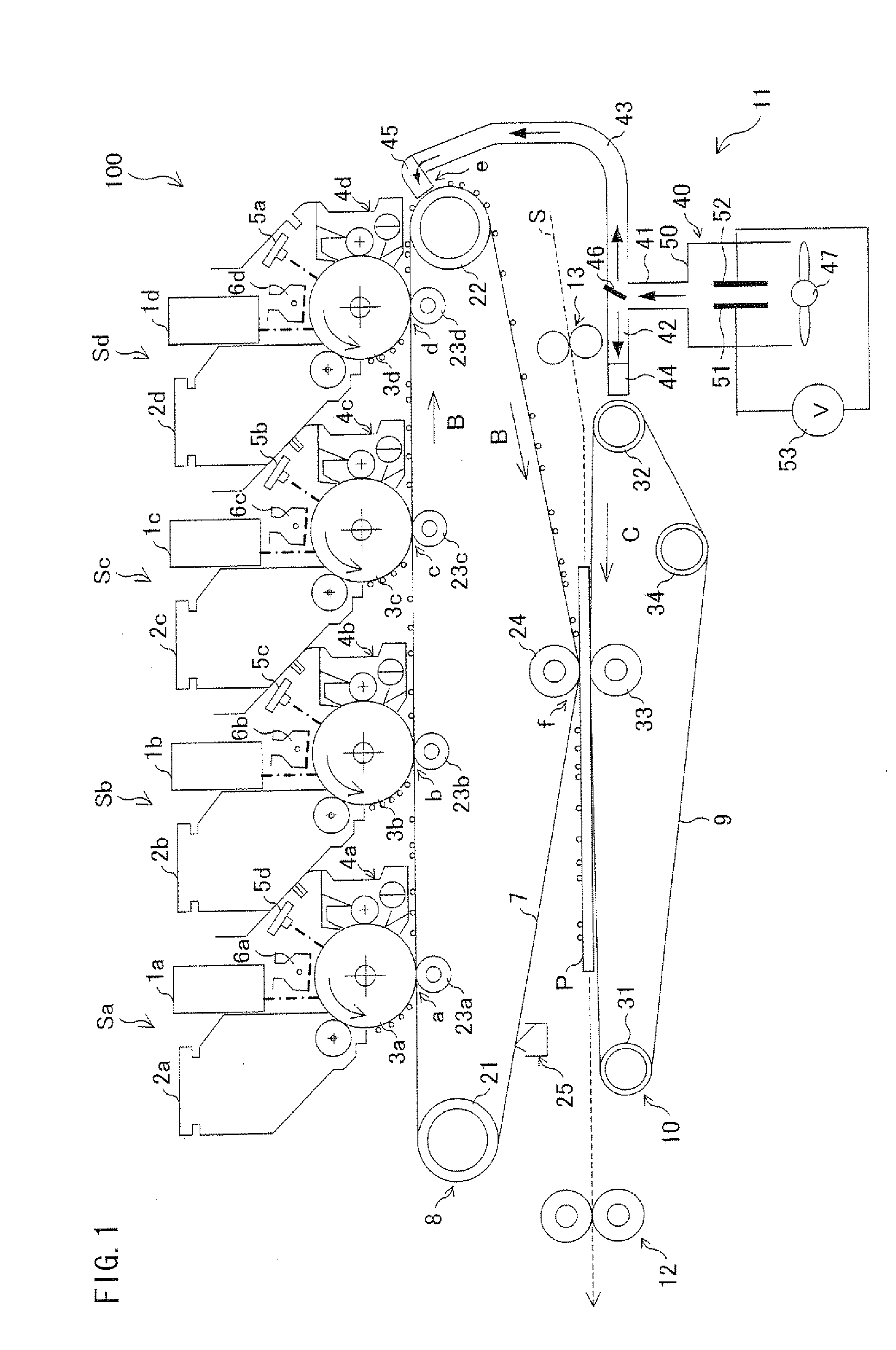
[0023]FIG. 1 is a cross-sectional view schematically showing a structure of an image forming apparatus 100 according to the present embodiment. Note that the image forming apparatus 100 is a color tandem image forming apparatus that forms a multicolor or monochrome image on a recording paper sheet (recording material) in accordance with external image data or image data created by an image reading device (not shown).

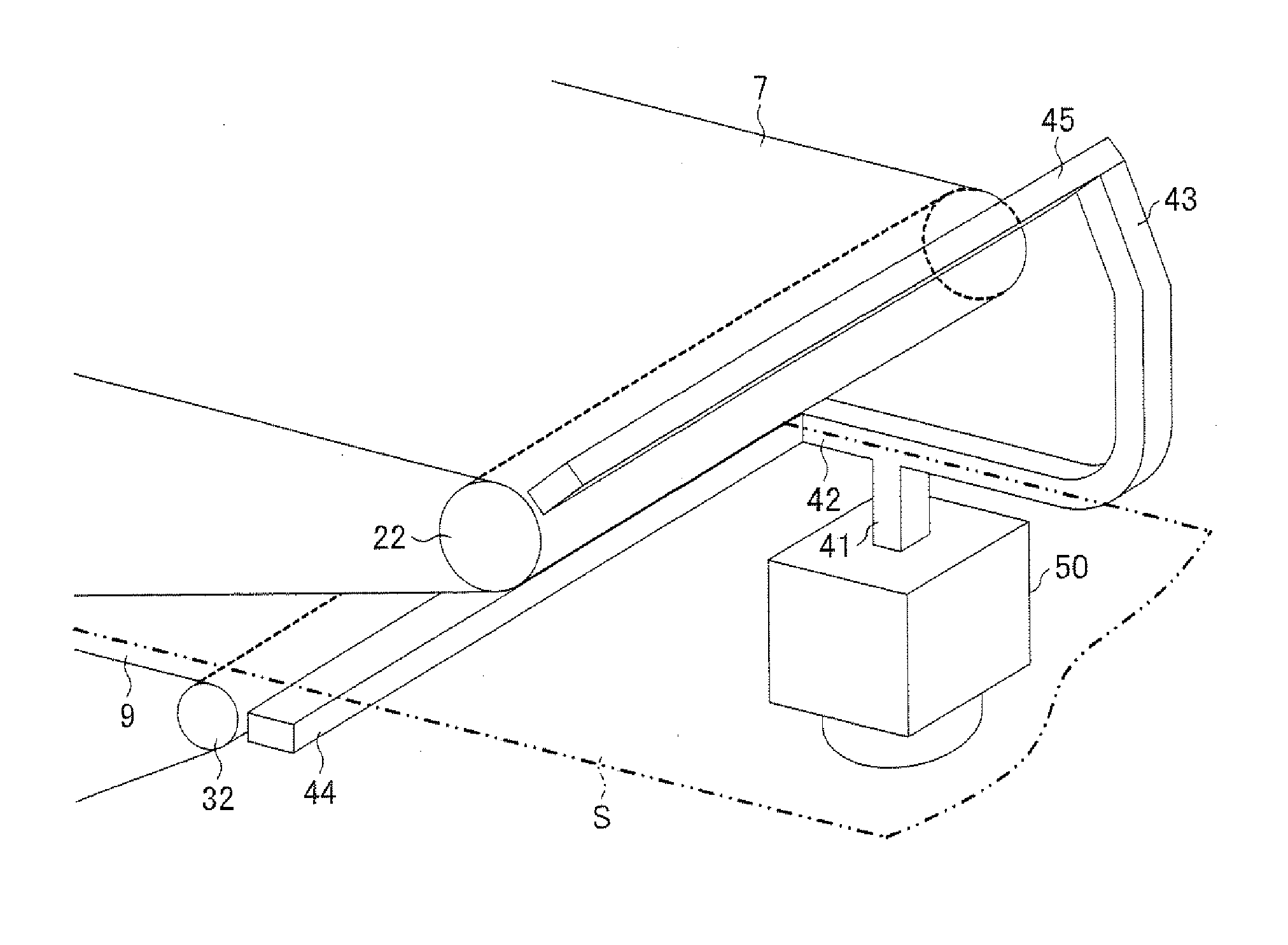
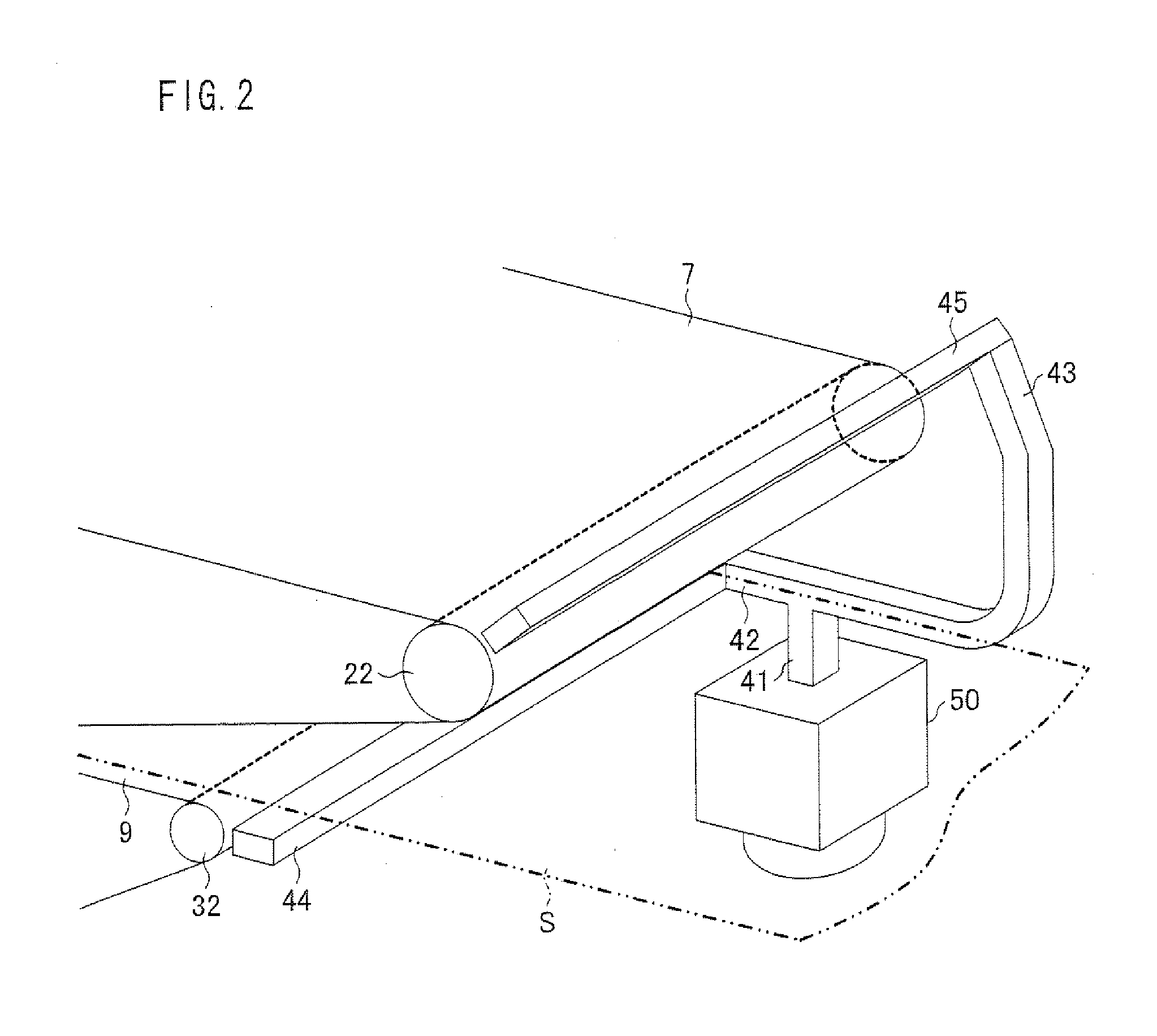
[0024]As shown in FIG. 1, the image forming apparatus 100 includes exposure units 1a to 1d, developing devices 2a to 2d, photosensitive drums 3a to 3d, cleaner units 4a to 4d, electricity-removing devices 5a to 5d, charging devices 6a to 6d, an intermediate transfer belt 7, an intermediate transfer belt unit 8, a paper sheet conveyer belt 9, a paper sheet conveyer belt unit 10, a charge imparting device 11, a fixing unit 12, a paper sheet conveying path S, and the like. Note that the operation of each o...


PUM


Abstract

Ions generated by the ion generating section are discharged from a paper sheet conveyer belt nozzle and an intermediate transfer belt nozzle, so that (i) a toner image transferred from a photosensitive drum onto an intermediate transfer belt and having yet to be transferred from the intermediate transfer belt onto a recording paper sheet and (ii) a paper sheet conveyer belt are charged. This makes it possible to more appropriately transfer a toner image onto a recording paper sheet from a photosensitive drum in an image forming apparatus, including a conveyer belt for conveying a recording paper sheet, in which a toner image formed on an image carrier is transferred onto an intermediate transfer body and the toner image is transferred from the intermediate transfer body onto a recording material; and to simultaneously prevent an increase in size of the image forming apparatus.

Description

[0001]This Nonprovisional application claims priority under 35 U.S.C. § 119(a) on Patent Application No. 322633 / 2006 filed in Japan on Nov. 29, 2006, the entire contents of which are hereby incorporated by reference.FIELD OF THE INVENTION[0002]The present invention relates to electrophotographic image forming apparatuses. More specifically, the present invention relates to an image forming apparatus including (i) an intermediate transfer body for conveying a toner image transferred from an image carrier onto the intermediate transfer body and transferring the toner image onto a recording material and (ii) conveying means for supporting and conveying the recording material.BACKGROUND OF THE INVENTION[0003]Conventionally, there has been known an image forming apparatus in which a toner image formed on an image carrier is transferred onto an intermediate transfer body and the toner image thus transferred onto the intermediate transfer body is transferred onto a recording material (e.g....

Claims


Application Information

Patent Timeline
Patent Type & Authority Applications(United States)
IPC IPC(8): G03G15/05
CPCG03G15/161G03G2215/1623G03G15/168
Inventor MASUDA, YOSHIAKI
Owner SHARP KK
Why Eureka
Try Eureka