

Fixing apparatus and image forming apparatus
- Summary
- Abstract
- Description
- Claims
- Application Information
AI Technical Summary
Benefits of technology
Problems solved by technology
Method used
Image

Examples
first embodiment
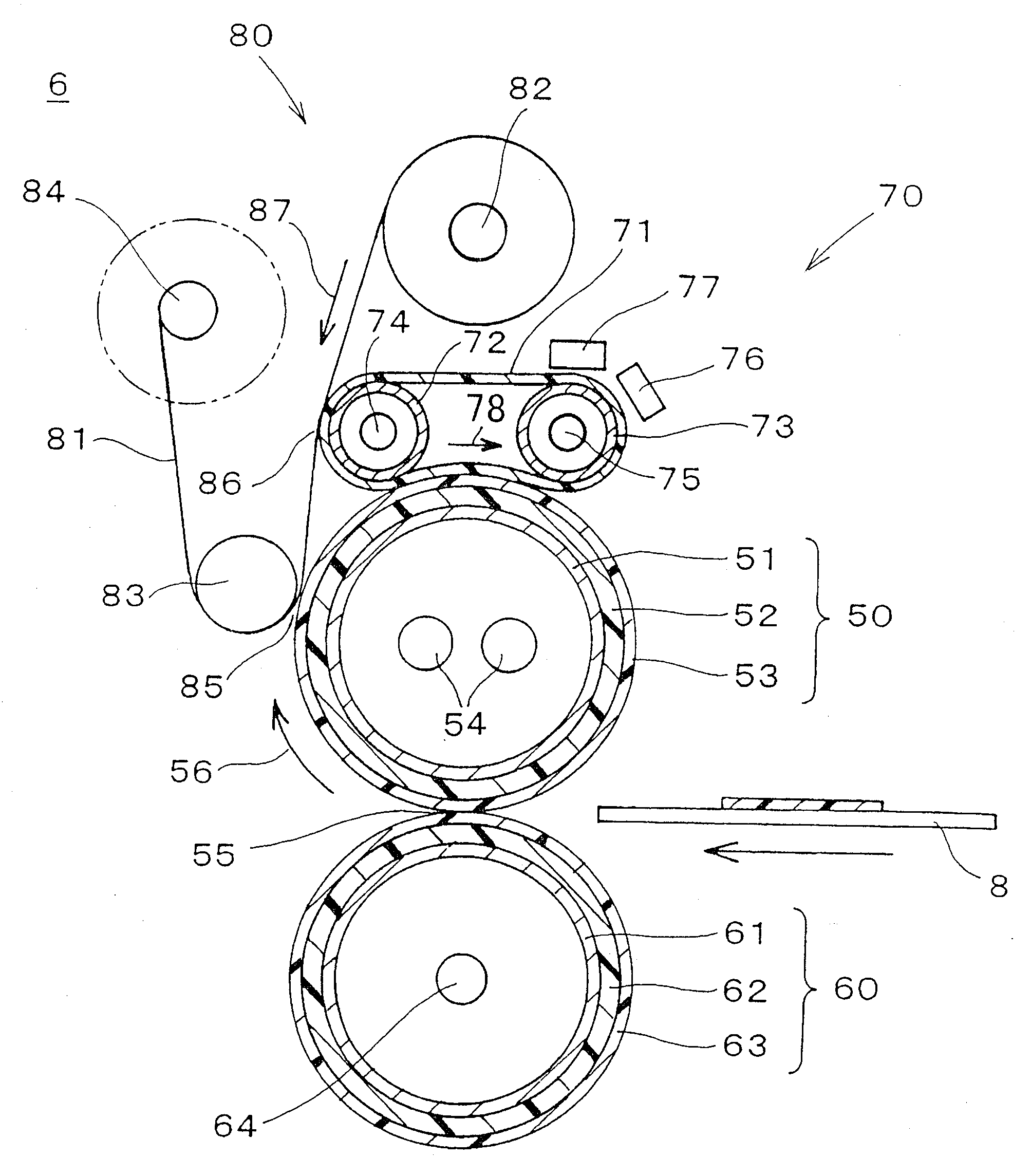
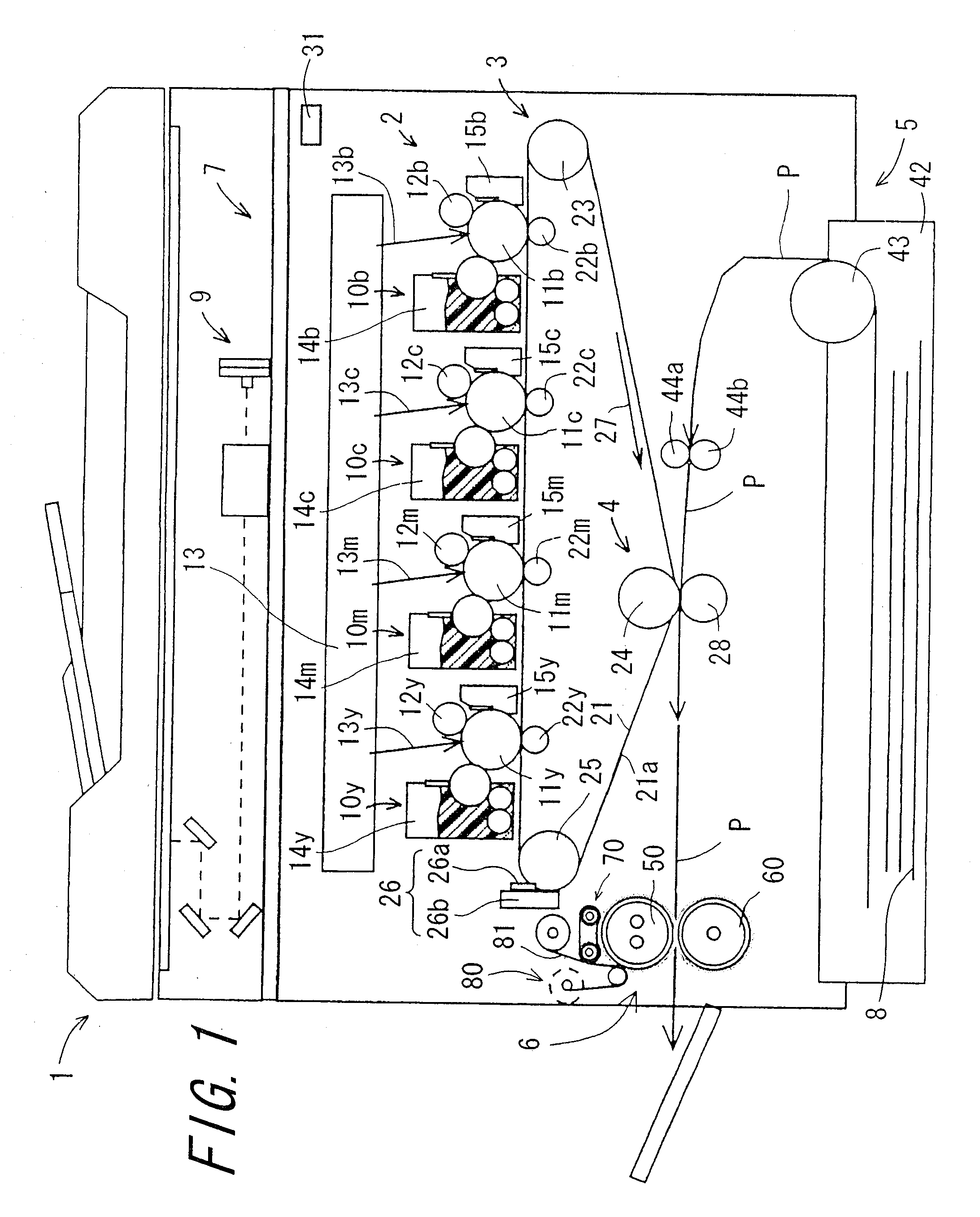
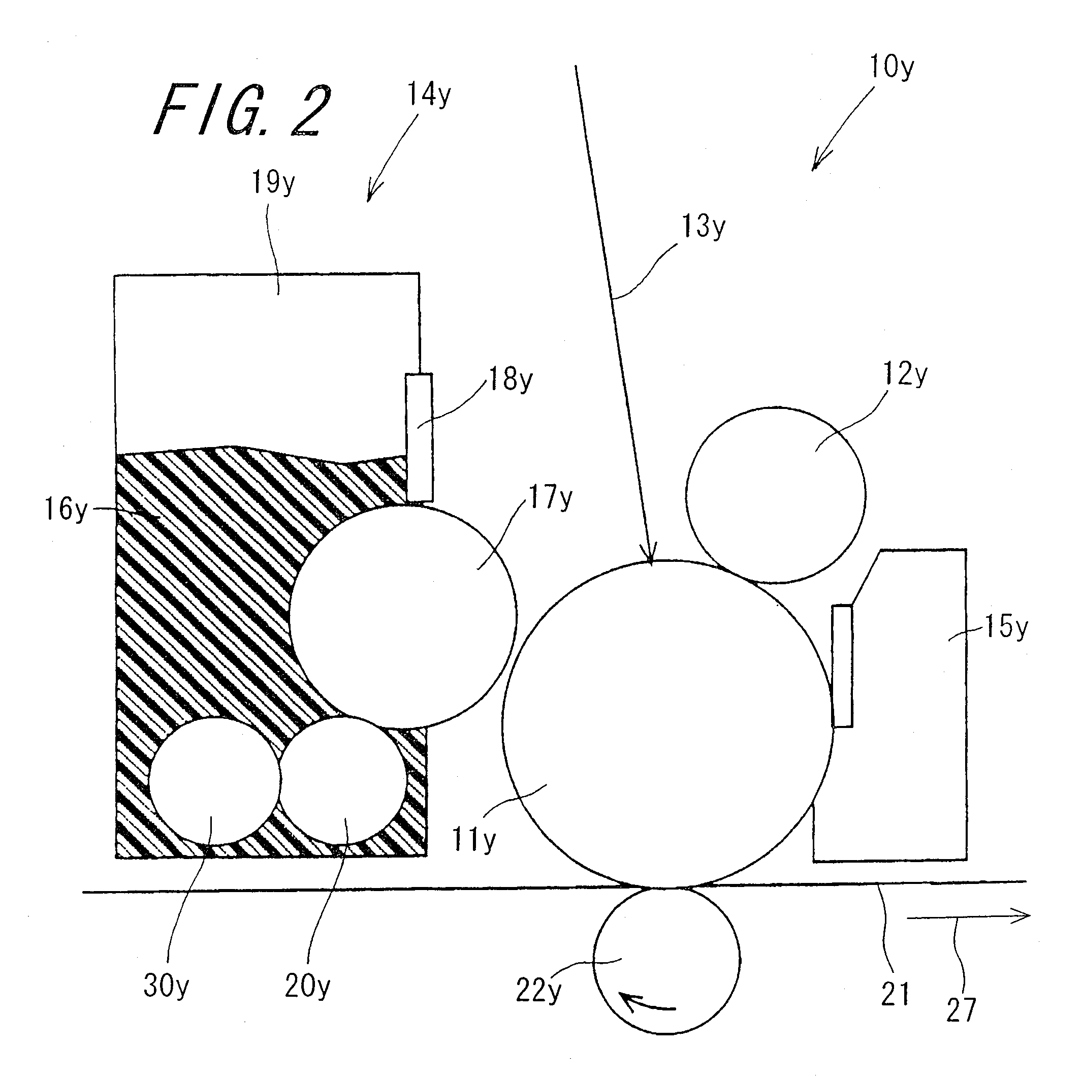
[0054]FIG. 1 is a sectional view schematically showing a configuration of an image forming apparatus 1 according to one embodiment of the invention. FIG. 2 is an enlarged sectional view showing a configuration of chief part of the image forming apparatus 1 shown in FIG. 1. FIG. 3 is a sectional view schematically showing a configuration of a fixing apparatus 6 according to the invention. FIG. 4 is an enlarged sectional view showing a configuration of chief part of the fixing apparatus 6 shown in FIG. 3. The image forming apparatus 1 is an electrophotographic image forming apparatus in tandem configuration which forms an image in a manner that toner images of four colors of yellow, magenta, cyan, and black are sequentially transferred and overlaid on top of one another to thereby form a multicolor toner image, and the multicolor toner image is fixed on a recording medium. The image forming apparatus 1 includes a toner image forming section 2, an intermediate transfer section 3, a sec...
second embodiment
[0088]FIG. 5 is a sectional view schematically showing a configuration of a fixing apparatus 6a according to a The fixing apparatus 6a is similar to the fixing apparatus 6, and corresponding parts will be denoted by the same reference numerals, and descriptions thereof will be omitted. The fixing apparatus 6a is characterized in that the feeding roller 82 is driven to rotate in a clockwise direction to feed the web 81, and a rest of the configuration of the fixing apparatus 6a is the same as that of the fixing apparatus 6. In the configuration of the fixing apparatus 6a, a feeding position where the web 81 is fed from the feeding roller 82 is shifted upward in the vertical direction, that is, a direction of an arrow 91, as an amount of the web 81 taken up by the winding roller 84 increases. As a result, an angle formed by the web 81 and the heating belt 71 gradually becomes larger at the second cleaning nip portion 86. A contact width d gradually becomes shorter between the web 81 ...
third embodiment
[0089]FIG. 6 is a sectional view schematically showing a configuration of a fixing apparatus 6b according to the invention. The fixing apparatus 6b is similar to the fixing apparatus 6, and corresponding parts will be denoted by the same reference numerals, and descriptions thereof will be omitted. The fixing apparatus 6b has the same configuration as that of the fixing apparatus 6 except that the fixing apparatus 6b includes an external heating section 70a instead of the external heating section 70. The external heating section 70a includes a first pressure-contact roller 72. The first pressure-contact roller 72 has the same configuration as that of the first pressure-contact roller 72 disposed in the external heating section 70, and serves as a heating roller. The web 81 contacts with a surface of the first pressure-contact roller 72 by being pressed thereon in a state where the web 81 is tensioned between the feeding roller 82 and the web pressure-contact roller 83 without slack....
PUM
 Abstract
Description
Claims
Application Information