Transferring device having two devices for cleaning a transferring member, and image forming apparatus

a technology of transferring device and transferring roller, which is applied in the direction of electrographic process apparatus, instruments, optics, etc., can solve the problems of the cleaning ability did not last long, and the paper powder caught between the cleaning blade and the second transferring roller stays for a long tim

Active Publication Date: 2008-05-29
RICOH KK
View PDF10 Cites 21 Cited by
  • Summary
  • Abstract
  • Description
  • Claims
  • Application Information

AI Technical Summary

Benefits of technology

[0019]It is to be noted that the present invention may be used with any t

Problems solved by technology

However, the good cleaning ability did not last long, and the toner residue on the back side of sheet exceeding tolerance level began to occur comparatively in a short term.
However, in the image forming apparatus which has relativel

Method used


Image

  • Transferring device having two devices for cleaning a transferring member, and image forming apparatus
  • Transferring device having two devices for cleaning a transferring member, and image forming apparatus
  • Transferring device having two devices for cleaning a transferring member, and image forming apparatus

Examples


Embodiment Construction

[0026]In describing preferred embodiments illustrated in the drawings, specific terminology is employed for the sake of clarity. However, the disclosure of this patent specification is not intended to be limited to the specific terminology so selected and it is to be understood that each specific element includes all technical equivalents that operate in a similar manner.

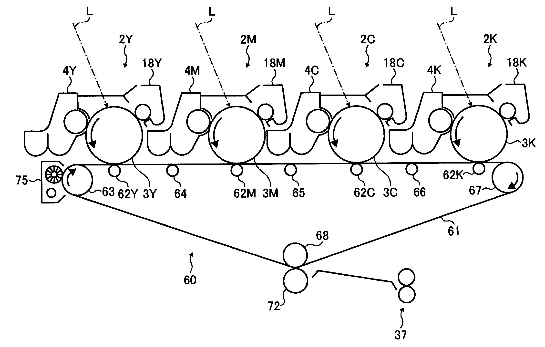
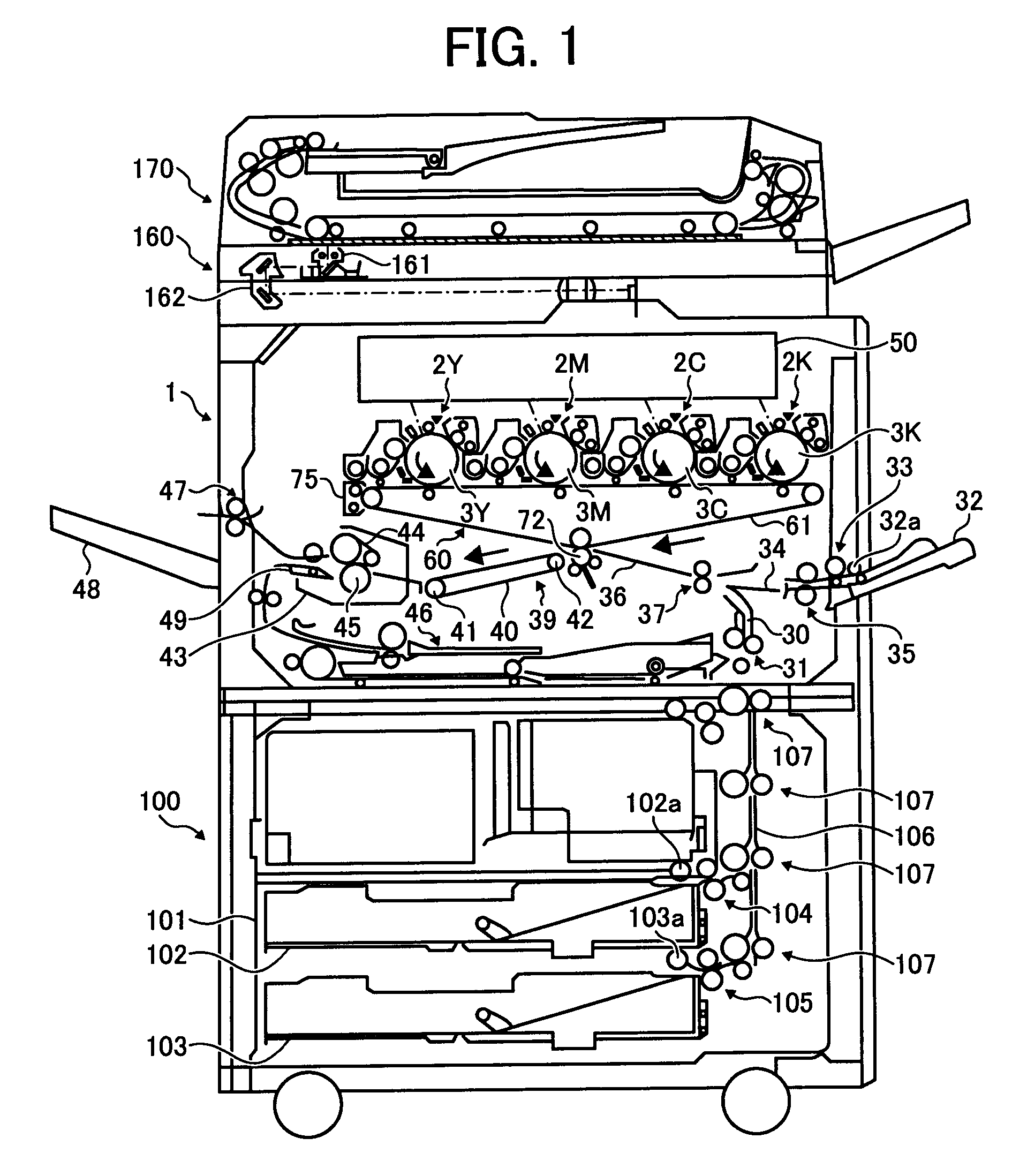
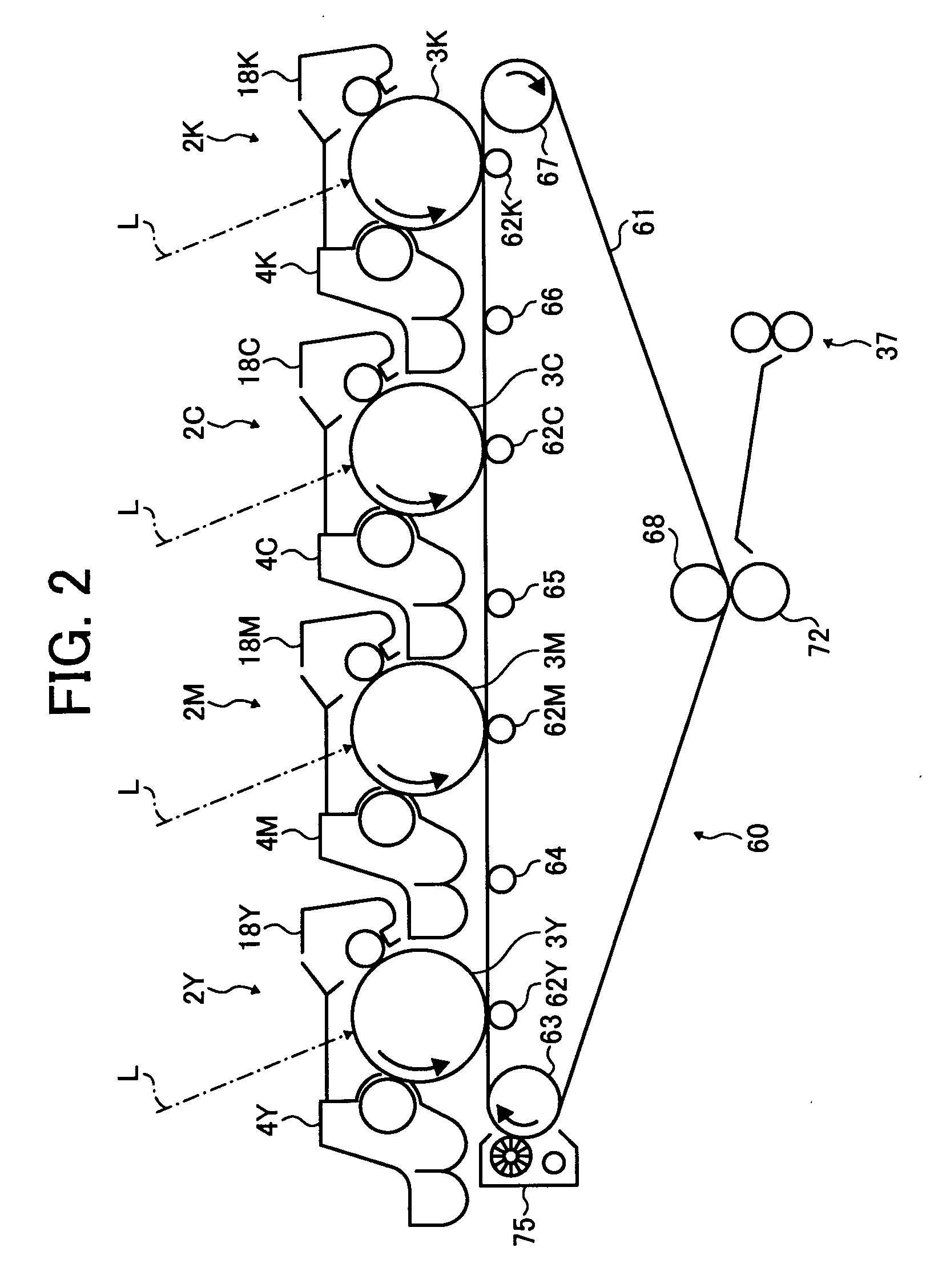
[0027]Referring now to the drawings, wherein like reference numerals designate identical or corresponding parts throughout the several views, preferred embodiments of the present invention are described. Referring to FIG. 1, a structure of an image forming apparatus is shown as an example of an image forming apparatus according to an exemplary embodiment of the present invention. The image forming apparatus includes an image forming unit formed of an image forming section 1 and a sheet feed unit 100, a scanner 160, and a document carrying unit or automatic document feeder 170. The scanner 160 is mounted on the image...


PUM


Abstract

A transferring device installed in an image forming apparatus includes an image bearing member configured to bear toner images on the surface. There is a transferring member configured to contact the image bearing member to form a transferring nip. A lubricant supplying member is configured to supply a lubricant to the surface of the transferring member, and there is a transferring member cleaning member such as a blade configured to remove residual toner and which contacts the surface of the transferring member. There is also a foreign material removing member configured to remove residual foreign material from the surface of the transferring member.

Description

CROSS-REFERENCE TO RELATED APPLICATIONS[0001]The present application claims priority to Japanese patent application no. 2006-319156, filed in the Japan Patent Office on Nov. 27, 2006, the disclosure of which is incorporated by reference herein in its entirety.BACKGROUND OF THE INVENTION[0002]1. Field of the Invention[0003]The present invention relates to a transferring device, a method and structure for cleaning the transferring device, and an image forming apparatus that includes the transferring device.[0004]2. Discussion of Background[0005]A transferring device transfers toner images formed on an image bearing member to a sheet at a transferring nip between a transferring member, e.g. a transferring roller, and the image bearing member. In this transferring device, toner residue may be picked up on the back side of a sheet at the transferring nip.[0006]Before the sheet is transferred to the transferring nip, toner on the surface of the image bearing member are transferred to the ...

Claims


Application Information

Patent Timeline
IPC IPC(8): G03G21/00
CPCG03G15/161G03G2221/0026G03G2221/0005
Inventor MIMBU, RYUUICHI
Owner RICOH KK
Why Eureka
Try Eureka