Concrete Screws

a screw and concrete technology, applied in the field of screws, can solve the problems of time-consuming screwing, inconvenient screwing, and time-consuming screwing, and achieve the effect of reducing screwing time and increasing screwing efficiency

Inactive Publication Date: 2008-05-29
CHANG CHEN CHIH +2
View PDF0 Cites 22 Cited by
  • Summary
  • Abstract
  • Description
  • Claims
  • Application Information

AI Technical Summary

Benefits of technology

[0010]The objects of the present invention are to provide a concrete screw for increasing the screwing efficiency and reducing the screwing time.

Problems solved by technology

While screwing, due to that the threads 13 lacks of the screwing intensity and can not self-drill into the wall 10, users need to drill a bore via a drilling machine in advance (not shown in the figures) and subsequently screw the screw 1 into the wall 10, which would take lots of time and cause inconvenience in screwing.
However, there are still some disadvantages while in operation:
However, it would substantially spend some time screwing the anchor into the wall.
However, it would be inconvenient and inefficient for users while operating.

Method used


Image

  • Concrete Screws
  • Concrete Screws
  • Concrete Screws

Examples


Embodiment Construction

[0022]Before the present invention is described in greater detail, it should be noted that the similar elements are denoted by the same reference numerals throughout the disclosure.

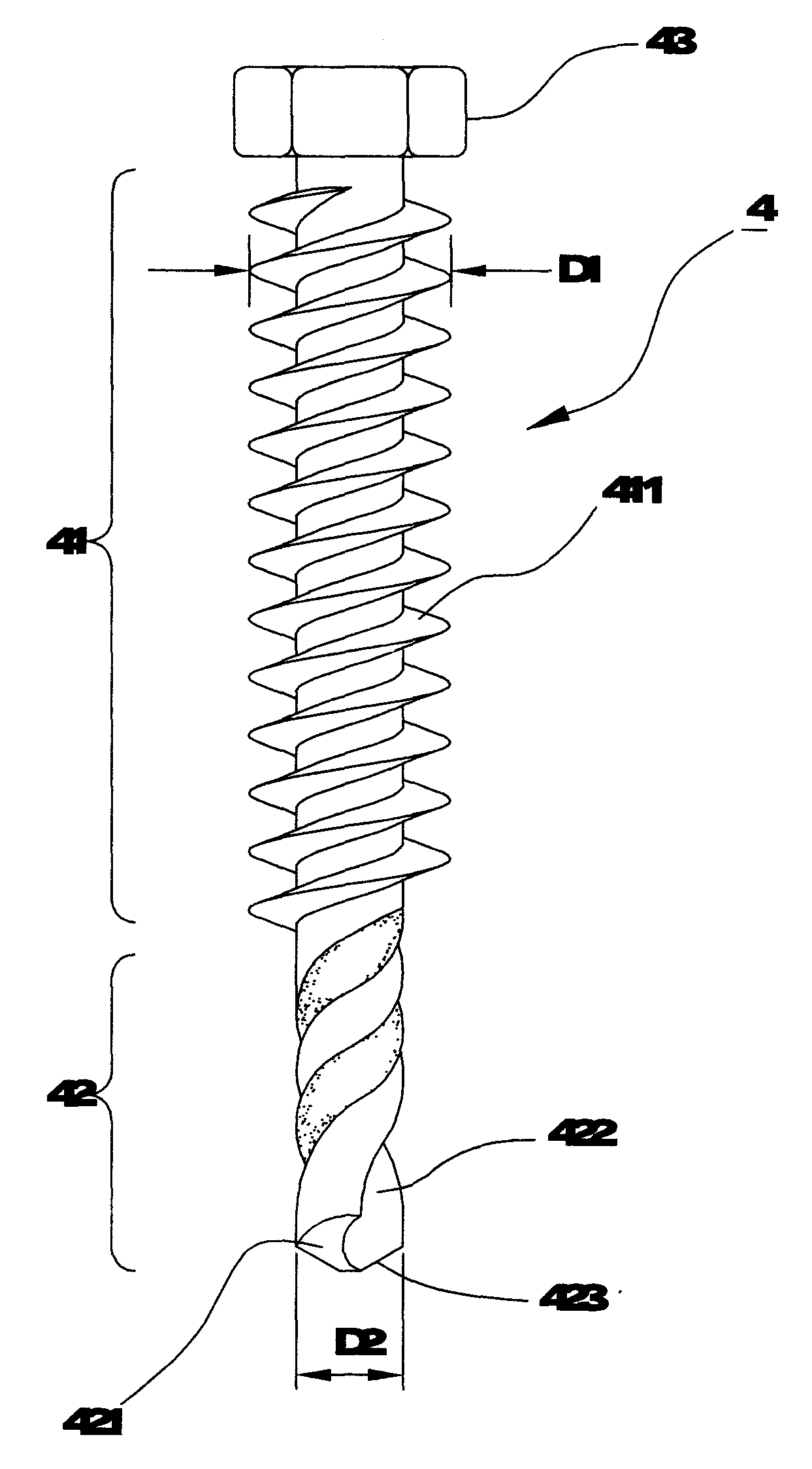
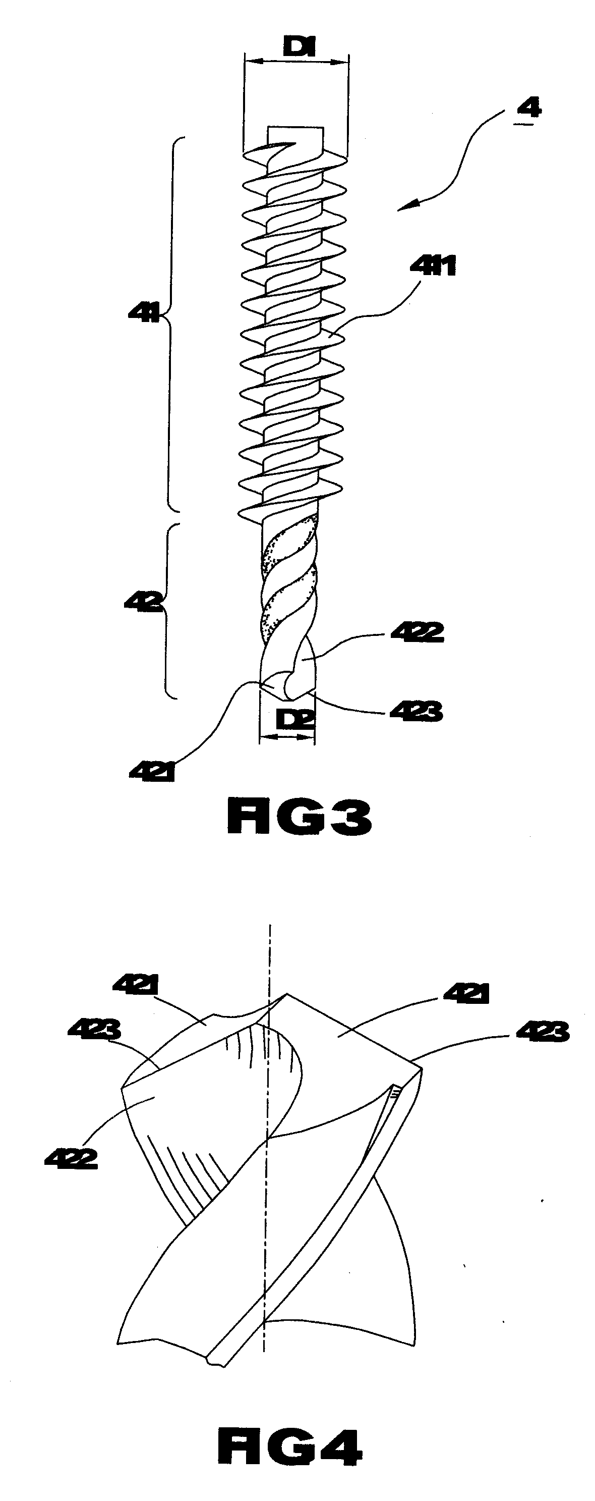
[0023]Referring to FIGS. 3 and 4, the concrete screw 4 of the first preferred embodiment comprises a threaded portion 41 and a helical conveying portion 42 disposed adjacent to the threaded portion 41; wherein, a plurality of threads 411 are spirally disposed on the threaded portion 41; furthermore, the outer diameter èD1è of the threads 411 of the threaded portion 41 is greater than the diameter èD2è of the helical conveying portion 42; the helical conveying portion 42 comprises two angled surfaces 421 formed at the distal end thereof, and two flutes 422 are respectively defined between the angled surfaces 421 and extended axially to the helical conveying portion 42; a cutting edge 423 is thus formed on the intersection of one side of each of the angled surfaces 421 and each of the flutes 422.

[0024]As sh...


PUM


Abstract

The present invention pertains to a concrete screw comprising a threaded portion with threads spirally disposed thereon and a helical conveying portion. In particular, the outer diameter of the threads is greater than the diameter of the helical conveying portion, in which two angled surfaces formed on the end thereof; two flutes are respectively defined between the angled surfaces, a cutting edge is formed on the intersection of one side of each of angled surfaces and two flutes. While screwing, the screw can directly and facilely be firmly screwed into the wall, thus greatly saving the screwing time and increasing the screw efficiency.

Description

BACKGROUND OF THE INVENTION[0001]1. Field of the Invention[0002]The present invention relates to a screw, in particular a concrete screw that can facilitate the users to save the screwing time and to increase the screwing efficiency.[0003]2. Description of the Related Art[0004]Typically, users usually exert a screw or an anchor to fasten the objects to the wall, such as a concrete, masonry, or other rigid materials. As referring to FIG. 1, a conventional screw 1 comprises a screw head 11 and a shank 12 connected to the head 11; wherein, a plurality of threads 13 are spirally disposed on the shank 12. While screwing, due to that the threads 13 lacks of the screwing intensity and can not self-drill into the wall 10, users need to drill a bore via a drilling machine in advance (not shown in the figures) and subsequently screw the screw 1 into the wall 10, which would take lots of time and cause inconvenience in screwing.[0005]An anchor 3 as shown in FIG. 2 comprises a shank 31, an anch...

Claims


Application Information

Patent Timeline
Patent Type & Authority Applications(United States)
IPC IPC(8): F16B25/10
CPCF16B5/0275F16B25/103F16B25/0084F16B25/0026
Inventor CHANG, CHEN-CHIHYANG, LI-HSUNYANG, PING-HUNG
Owner CHANG CHEN CHIH
Why Eureka
Try Eureka