Casing For a Sealed Battery

a bipolar battery and sealed technology, applied in the field of sealed bipolar batteries, can solve the problems of affecting the solution is not cost effective for mass manufacturing, and the finished battery assembly can be detrimental to the cost, volume and weight of the resulting battery assembly, etc., to achieve the effect of adequate and adequate uniform pressur

Inactive Publication Date: 2008-05-29
NILAR INT AB
View PDF11 Cites 37 Cited by
  • Summary
  • Abstract
  • Description
  • Claims
  • Application Information

AI Technical Summary

Benefits of technology

[0007]An object of the present invention is to provide a casing for a sealed bipolar battery having a battery stack that can maintain adequate and adequately uniform pressure across the battery compared to prior art casings.
[0009]An advantage with the present invention is that it is less expensive to manufacture, can result in a smaller part count in a finished battery assembly, and can result in less weight and volume in the finished battery for a given cell stack. This is especially advantageous for batteries comprised of a smaller cell stack, where the casing typically occupies a larger fraction of the total weight and volume of the finished assembly when compared to batteries made with a larger cell stack.
[0010]Another advantage is that the present invention provides a casing where externally applied means are not necessary to maintain the shape of the battery casing, which in turn will reduce the cost for manufacturing the battery.

Problems solved by technology

While this mechanical approach to managing the forces on a cell stack can be effective, it is a heavy and bulky solution that is not cost effective for mass manufacturing.
This approach has similar weight, volume and cost drawbacks, in addition to the need to provide the pressurized fluid to the bellows.
The inclusion of such an additional complaint part in the finished battery assembly can be detrimental to the cost, volume and weight of the resulting battery assembly.

Method used


Image

  • Casing For a Sealed Battery
  • Casing For a Sealed Battery
  • Casing For a Sealed Battery

Examples


first embodiment

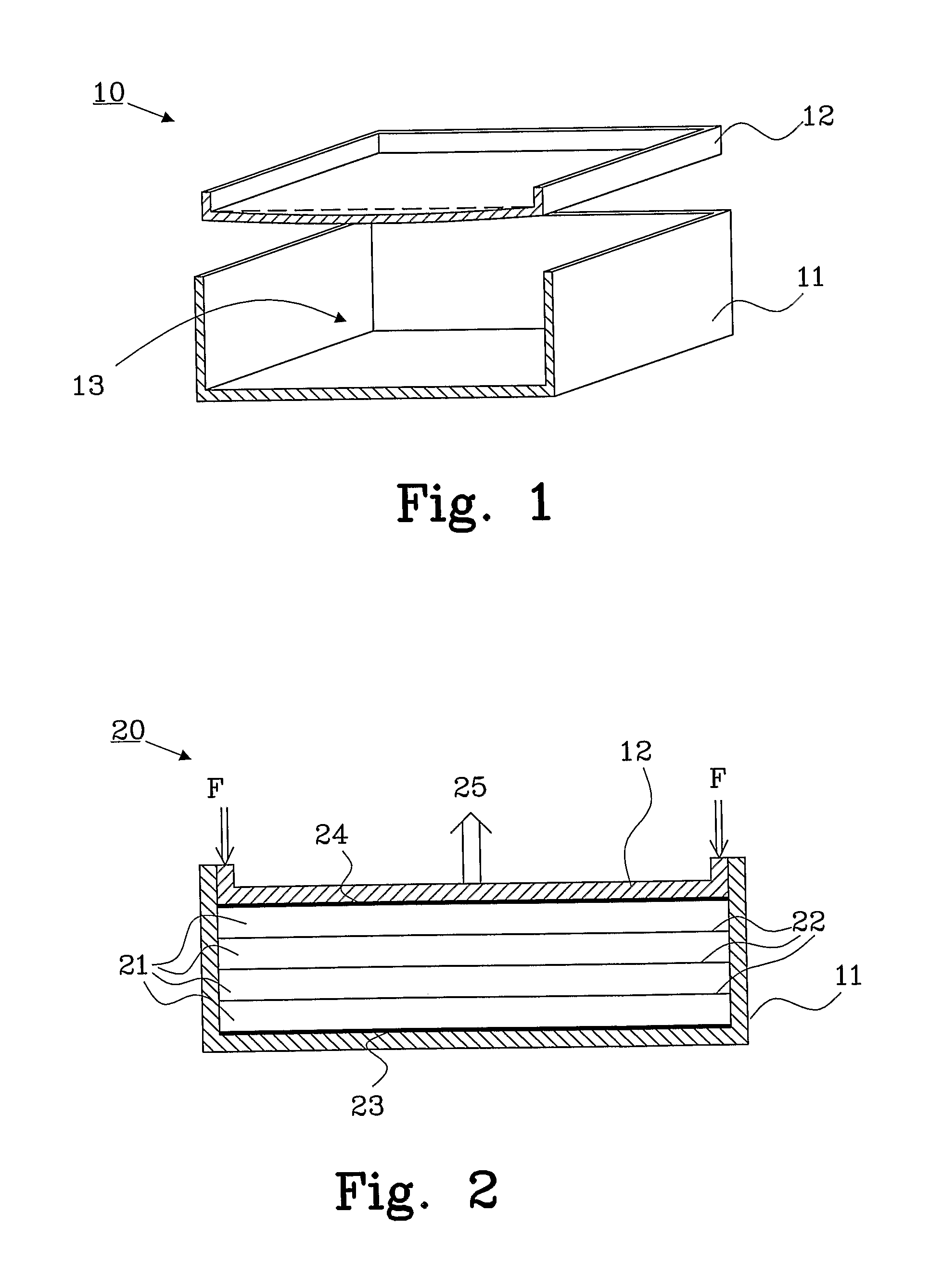
[0034]the present invention is described in connection with FIG. 1, which is a partially cross-sectional view of a non-joined battery casing 10 comprising a lower part 11 and an upper part 12. The upper part 12 is designed to be inserted into the lower part 11 and fasteners (not shown) or a welding will be provided to hold the part together. Battery cells (not shown) arranged in a cell stack will be assembled in the space 13 that is created inside the joined parts 11, 12. Small holes for battery terminal access (not shown) may be provided in the upper part 11 and lower part 12.

[0035]In this example the upper part 12, i.e. the lid, is provided with an arrangement that will prevent the casing from breaking and maintaining adequate and adequately uniform pressure across the cell stack. By preloading the part with a spring force, which is the result of creating an inverted pre-bowed shape of the upper part 12, a mechanically compliant arrangement is provided together with an arrangement...

second embodiment

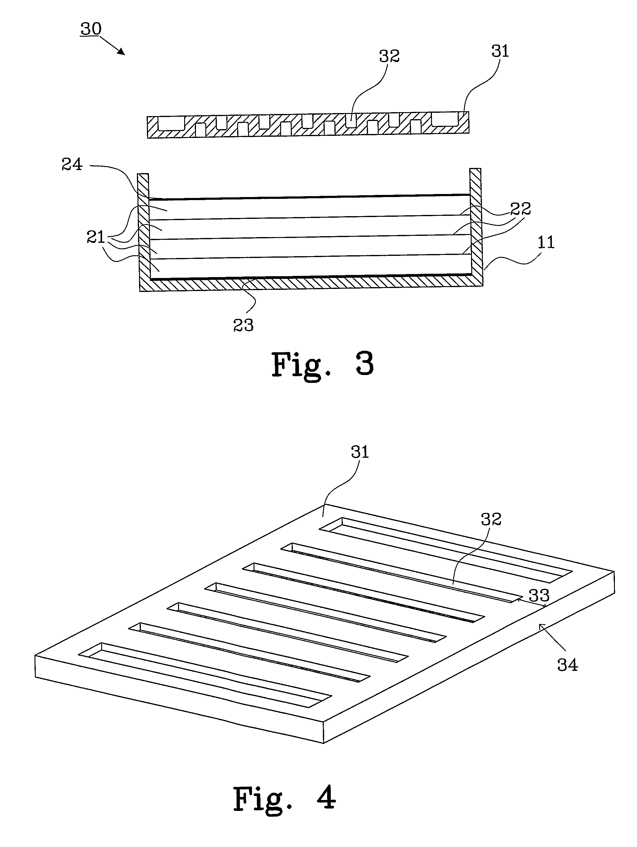
[0039]FIG. 3 shows a casing according to the present invention, comprising a case 11 and a lid 31 that has a corrugated shape, each corrugation is denoted 32. FIG. 3 illustrates the non-joined casing in connection with a bipolar battery 30 during the assembling process, where identical parts of the battery have been denoted with the same reference numerals as in FIG. 2.

[0040]The corrugation in the lid 31 face will reduce the stress concentration by a factor of 2-4 times for the same load compared to prior art lids. Depending on the material and area of face, it does have some impact on the stiffness of the face, but it is not always stiffer than a non-corrugated face. The goal of the corrugation is to reduce the magnitudes of stress concentrations, so that they are safely below the material's yield stress.

[0041]FIG. 4 shows a perspective view of the lid 31 in FIG. 3, where the corrugations 32 are shown more clearly. The corrugations do not extend across the complete width of the lid...

fourth embodiment

[0044]FIG. 7 shows a cross-sectional view of a battery 55 with a casing provided with optional compliant members 52 and 53. The assembly comprises a lower case part 11, a first optional compliant member 52, a positive endplate 23, a cell stack of four cells 21, a negative endplate 24, a second optional compliant member 53 and an upper case part 41. The optional compliant members will function as an extra compliant part in the battery in case the compliance in the casing is not sufficient.

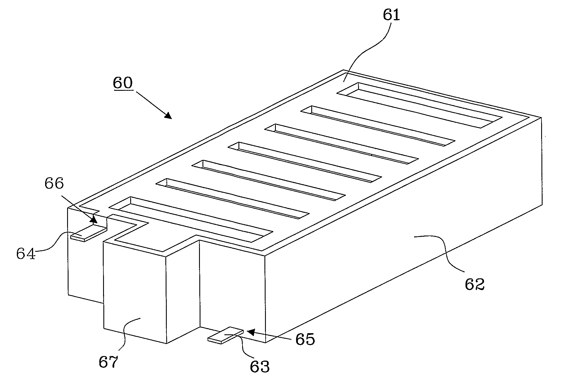
[0045]FIG. 8 shows an assembled casing 60 provided with means to connect each endplate inside the battery casing with a positive terminal 63 and a negative terminal 64 without interfering with the resilient and stress distribution function of the lid 61 and the case 62. A hole 65 is provided in the case 62 for the positive terminal connector 63 and a cut-out 66 is provided in the case for the negative terminal connector 64. Furthermore, a divider 67 is provided in the case 62 that will prevent direc...


PUM

PropertyMeasurementUnit
thicknessaaaaaaaaaa
pressureaaaaaaaaaa
shapeaaaaaaaaaa

Abstract

The present invention relates to a casing 10 for a sealed bipolar battery 20, 30, 50, 55, 60 comprising at least one battery cell 21, wherein each cell have electrodes with non-metallic substrates. The casing comprises at least two parts, an upper part 12, 31, 41, 61 and a lower part 11, 51, 62, that are joined together to form the casing of the battery. A mechanically compliant arrangement are built-in to the casing to reduce the forces on the cell stack caused by changes in cell thickness during operation, and a pressure means are built-in to the casing to distribute the pressure across the cell stack.

Description

TECHNICAL FIELD[0001]The present invention relates to a casing for a sealed bipolar battery, especially for a battery comprising electrodes with non-metallic substrates, as defined claim 1.BACKGROUND TO THE INVENTION[0002]A sealed bipolar battery, e.g. a NiMH bipolar battery, having a plurality of battery cells arranged in an electrochemical bipolar cell stack must have a casing that bears the forces that the cell stack applies to the casing. Each battery cell in a bipolar battery comprises a negative electrode and a positive electrode with a separator arranged between them. Each cell is separated from other cells by an electrically conductive biplate, and a positive endplate and negative endplate, respectively, are arranged on each side of the cell stack.[0003]Various mechanical casing and support methods have been used to direct and control the forces that are need for proper operation of an electrochemical bipolar cell stack.[0004]In the granted U.S. Pat. No. 5,547,777 by Richard...

Claims


Application Information

Patent Timeline
Patent Type & Authority Applications(United States)
IPC IPC(8): H01M2/02H01M50/10H01M50/112H01M50/147H01M50/578
CPCH01M2/0207H01M2/0242Y02E60/50H01M8/2475H01M8/248H01M2/0404Y02E60/10H01M50/112H01M50/147H01M8/247
Inventor HOCK, DAVIDJENSEN, KURTPUESTER, NEIL
Owner NILAR INT AB
Why Eureka
Try Eureka