Optimized multi-mode DFT implementation

a multi-mode dft and implementation technology, applied in the field of optimization multi-mode dft implementation, can solve the problems of inacceptable processing time of the order nsup>2 and process data vectors, and achieve the effect of moderate hardware complexity

Inactive Publication Date: 2008-05-29
NOKIA CORP
View PDF3 Cites 8 Cited by
  • Summary
  • Abstract
  • Description
  • Claims
  • Application Information

AI Technical Summary

Benefits of technology

[0005]It is therefore an object of the present invention to provide a fast DFT implementation for transforming signals with vector lengths other than 2x and moderate hardware complexity.
[0016]Accordingly, an implementation of non 2x-radix Fourier transformation can be achieved with moderate hardware complexity and with a wide range of vector lengths optimized for individual hardware implementations. Additionally, the order of operation number (especially the number of multiplications) and thus the reduced processing time can be reduced.

Problems solved by technology

A limitation of FFT is that it can only process data vectors which have a length in the form of 2x, where x is a positive integer.
Compared with FFT, a straight forward implementation of the DFT algorithm would result in unacceptable processing time of the order n2.

Method used


Image

  • Optimized multi-mode DFT implementation
  • Optimized multi-mode DFT implementation
  • Optimized multi-mode DFT implementation

Examples


first embodiment

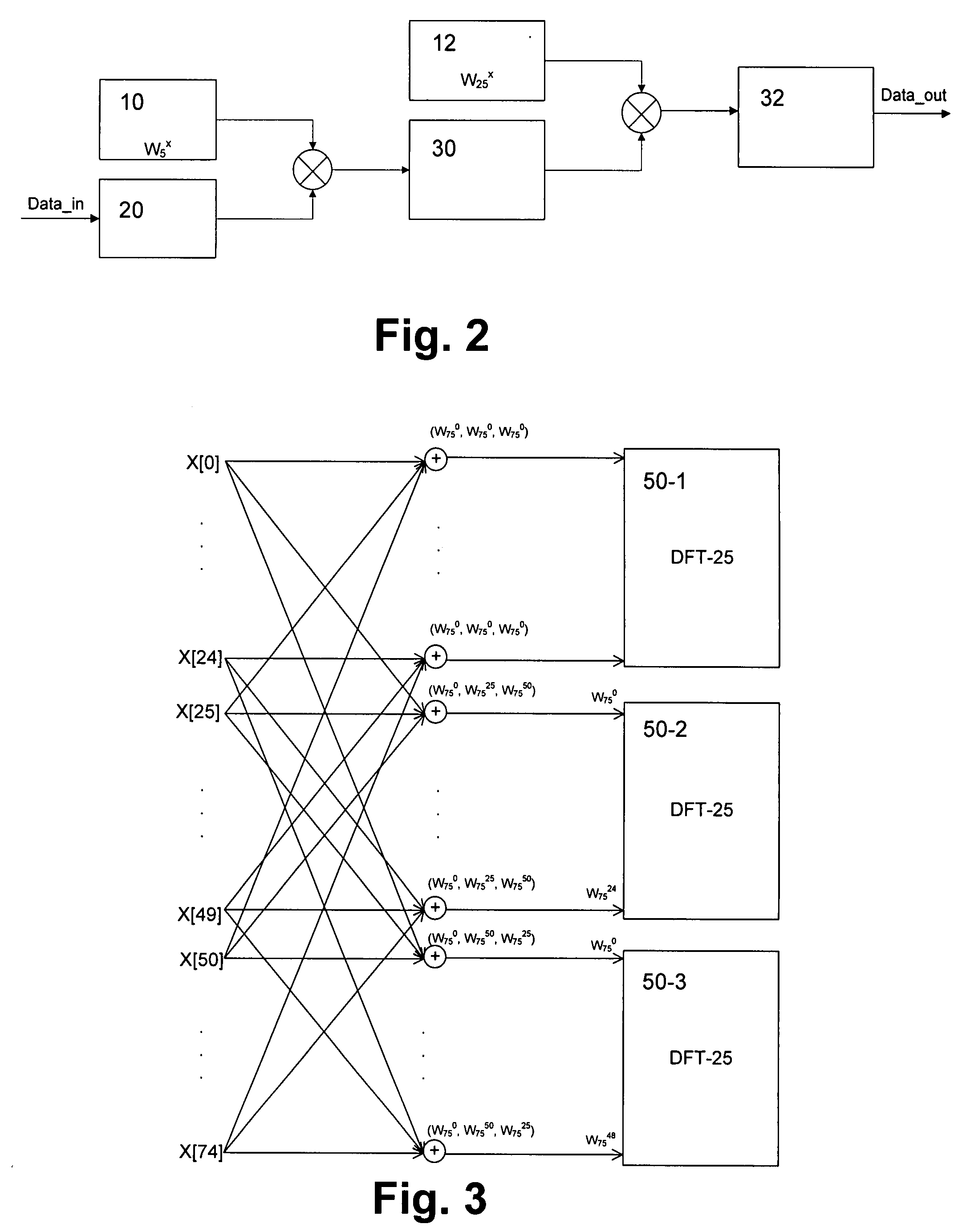
[0046]FIG. 2 shows a schematic block diagram of an implementation of the basic DFT-25 module according to the

[0047]Input data (X[i]) is supplied to a 5× or 5-times hold unit 20 and the stored samples are supplied to a first multiplier and multiplied with an assigned twiddle factor W5x generated in a first twiddle factor generating unit 10. Five successive outputs of the first multiplier are added in a first integrator unit 30 and then supplied to a second multiplier where the obtained sum is multiplied with another assigned twiddle factor W25x generated in a second twiddle factor generating unit 12. Again, five successive outputs of the second multiplier are added in a second integrator unit 32 to obtain the output data (Y[i]).

[0048]FIG. 3 shows a schematic data flow graph of a DFT-75 module according to the first embodiment based on the Cooley-Tukey algorithm and derived from three basic DFT-25 modules 50-1 to 50-3. It is again noted that not all transitions are shown with arrows f...

second embodiment

[0060]In the upper part of FIG. 7, the above DFT-75 module is shown as a combination of the block diagrams of FIGS. 2 and 4. It can be gathered that between the second and the third multiplication with the twiddle factors of the twiddle factor generating units 16 and 10, no other arithmetical operations are performed. The two multiplications with the twiddle factors can be combined into one addition and one multiplication:

a·Wx1y1·Wx2y2=a·jy1·2π / x1·jy2·2π / x2=a·j(y1 / x1+y2 / x2)·2π

[0061]As an example, the lower part of FIG. 2 shows an optimized block diagram of the DFT-75 implementation according to this embodiment with reduced number of multiplications. This implementation can be generalized for any other DFT implementation of length L, where L can be further factorized as:

L=a·b·c,

where a, b and c are positive integers. In case of the DFT-75 module, the factor “a” is 3, while “b” and “c” are 5.

[0062]FIG. 8 shows a schematic block diagram of a generalized DFT implementation according t...


PUM


Abstract

The present invention relates to a method and apparatus for implementing a discrete Fourier transformation (DFT) of a predetermined vector size, wherein at least one enhanced DFT module is provided by using at least one type of DFT module including multiplication by first and second types of twiddle factors in respective different multiplication stages separated by an intermediate integration stage, and generating the enhanced DFT module by combining the at least one type of DFT module with a recursive stage configured to multiply by a third type of twiddle factor and to selectively switch between a bypass function and a butterfly function in said recursive stage. Thereby, an implementation of non 2x-radix Fourier transformation can be achieved with moderate hardware complexity.

Description

FIELD OF THE INVENTION[0001]The present invention relates to a method and apparatus for implementing a discrete Fourier transformation (DFT) of a predetermined vector size.BACKGROUND OF THE INVENTION[0002]Many current communication systems are based on Orthogonal Frequency Division Multiplexing (OFDM) and related technologies. The Fourier transformation of a signal from time domain into frequency domain and vice versa is one of the most important processing modules in such systems. The fast Fourier transform (FFT) is an efficient algorithm to compute a DFT and its inverse. In general, FFTs are of great importance to a wide variety of other applications as well, e.g., digital signal processing for solving partial differential equations, algorithms for quickly multiplying large integers, and the like.[0003]A limitation of FFT is that it can only process data vectors which have a length in the form of 2x, where x is a positive integer. However, latest communication standards, e.g. EUTR...

Claims


Application Information

Patent Timeline
Patent Type & Authority Applications(United States)
IPC IPC(8): G06F17/14
CPCG06F17/142H04L27/263H04L27/265H04L27/2651
Inventor XU, YUHUANSCHWOERER, LUDWIG
Owner NOKIA CORP
Why Eureka
Try Eureka