
Force and Torque Measurements with Calibration and Auto Scale

a technology of force and torque and auto scale, which is applied in the field of electromechanical measurements of force and torque, can solve the problems of high error rate, difficult calibration of both in the field or the factory, and prior art methods of accuracy and measurement methods, so as to save time and effort, improve accuracy, and do the work safely and accurately

Inactive Publication Date: 2008-06-05
FARAG TAREK A Z
View PDF49 Cites 71 Cited by
  • Summary
  • Abstract
  • Description
  • Claims
  • Application Information

AI Technical Summary

Benefits of technology

"The invention is a device and method to measure the force or torque applied to a workpiece. The device has the advantages of being low cost, reliable, long life, fast response, small size, high accuracy, easy to calibrate, and compatible with other devices. It can measure the torque in real-time, independently of the position or angle at which the force is applied. The device can generate different signals based on the torque value, and can be powered and controlled remotely. It can be used in various fields and can be customized for different needs. The device has a display to display the torque measurements in different units and can be calibrated easily. It can also communicate and interface with other devices and can be used in a continuous or intermittent manner. The device can be manufactured in different forms and can be used in tight areas or in high-speed operations. The technical effects of the invention include improved accuracy, reliability, and efficiency in measuring force or torque, as well as the ability to measure it quickly and easily in different situations."

Problems solved by technology

The main disadvantages of the prior art methods are their accuracy and measurement methods.
They are difficult to calibrate both in the field or the factory, especially after normal or abnormal use, and at different operating conditions of temperature, humidity, dust, etc.
In the cases of impact wrenches, the error could be very high due to the variation of the inertia and the holding method (holding the tool firmly or loosely will change the impact force on the workpiece).
Other disadvantages are the large size of the sensors and the large inertia, which limit their response time and the applications.
Another disadvantage of the prior art is that there were no means to record or prove that the user abused the tool if the tool was damaged due to exceeding its design limits.
Another disadvantage of the prior art is that the user has no choices in displaying the value (peak, average), and most of them do not have the ability to measure the torque required to loosen a part.

Method used


Image

  • Force and Torque Measurements with Calibration and Auto Scale
  • Force and Torque Measurements with Calibration and Auto Scale
  • Force and Torque Measurements with Calibration and Auto Scale

Examples


Embodiment Construction

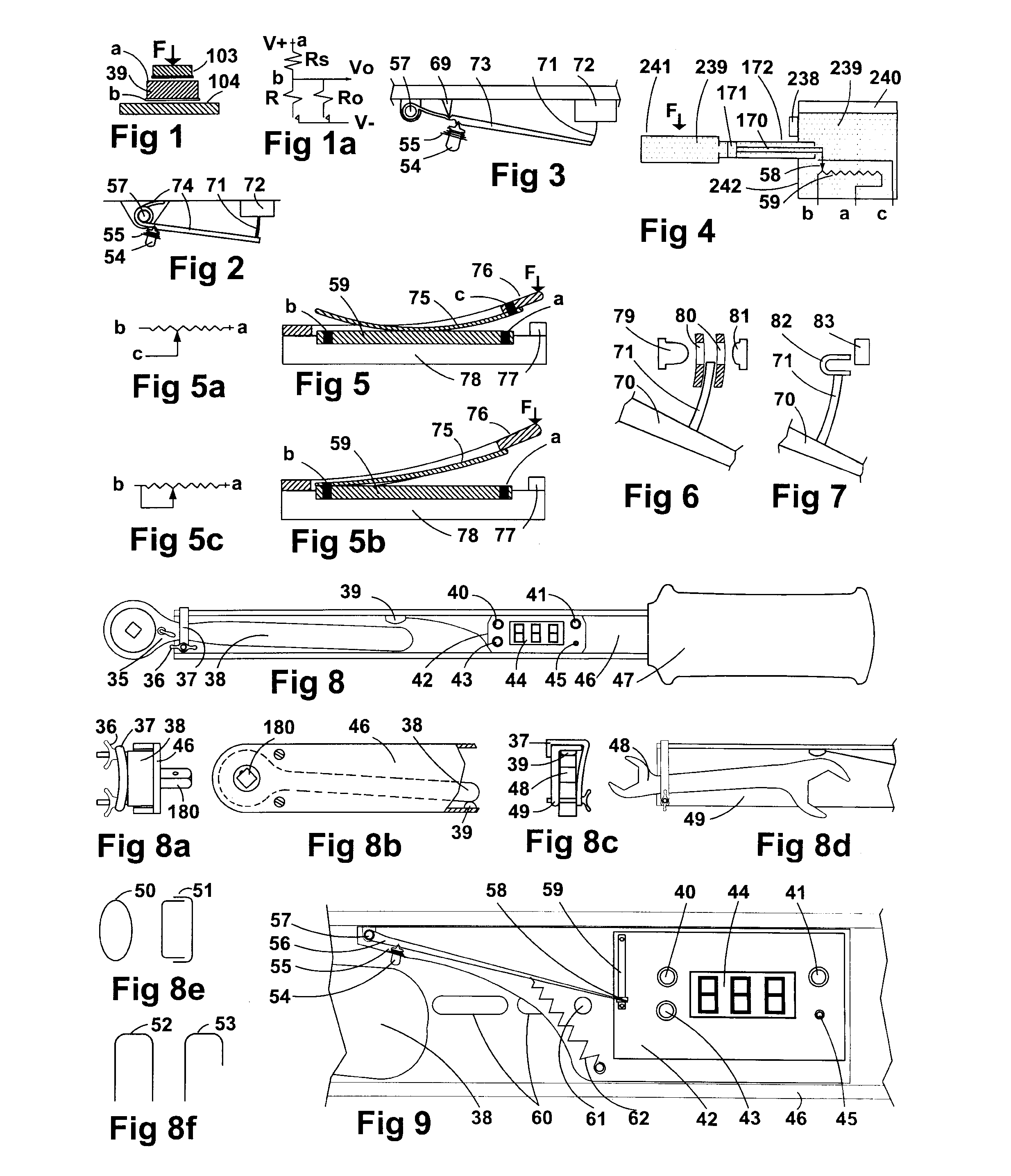
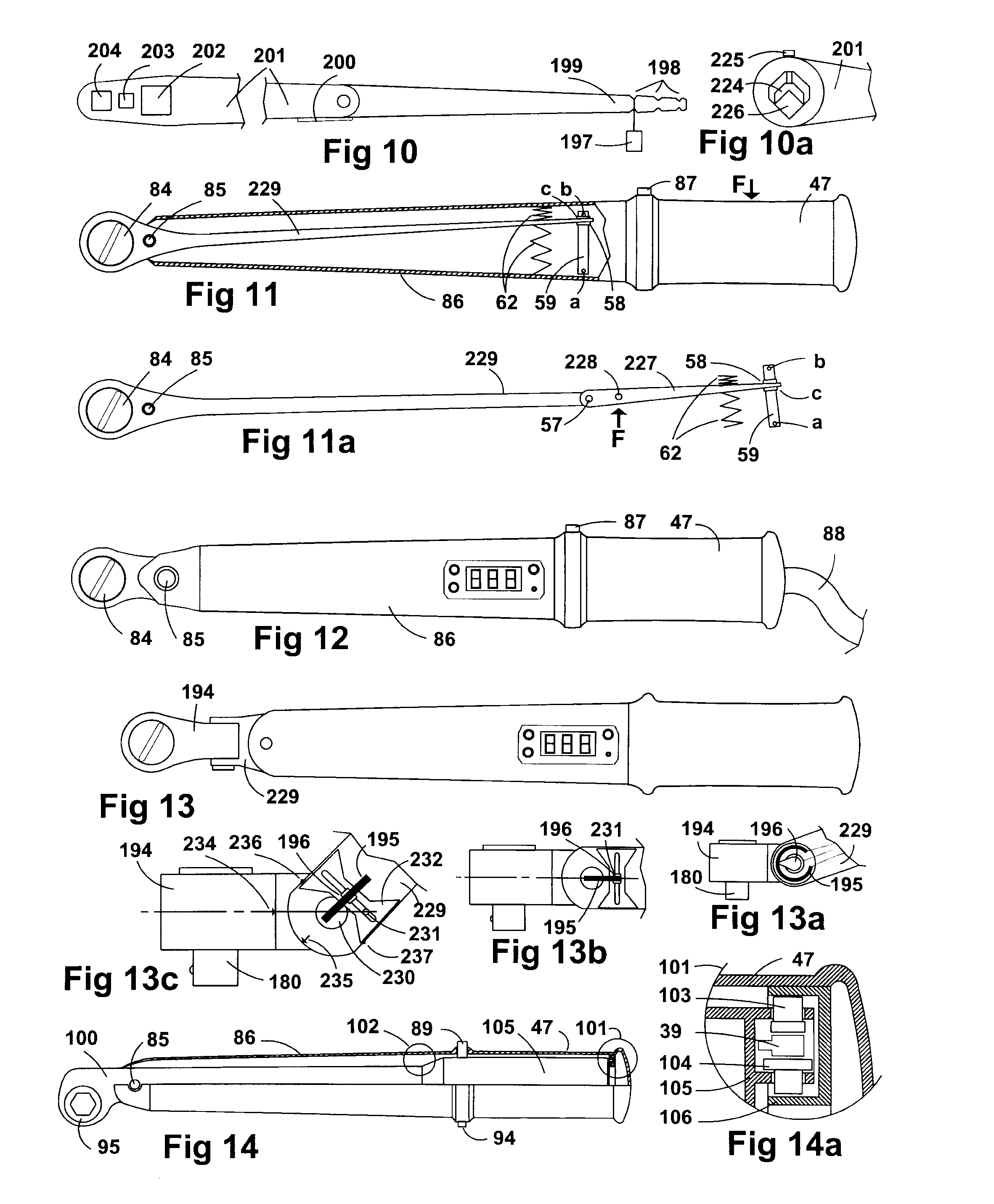
[0074]The two measurements of force and torque could be exchanged, with the understanding that the torque is the amount generated when multiplying; the force component perpendicular to the line from the point it acts on to the point where the torque measurement is made, by the distance between these two points. In the following description of embodiments and figures of this invention, measuring the force at a specific distance could be used to express the torque.

[0075]FIG. 1 shows a force sensor (39) with the force (F) applied on it. This sensor (39) is usually made from a polymer or elastomeric material, which has a resistance that changes proportional to the force applied on it. The resistance is measured between the first electrode (a) and the second electrode (b). This kind of sensor is best suited for this application because it has small dimensions (could be of a thickness less than 0.5 mm and a diameter less than 15.0 mm), easy to use, and is simple to condition electronicall...


PUM

PropertyMeasurementUnit
diameteraaaaaaaaaa
diameteraaaaaaaaaa
forceaaaaaaaaaa

Abstract

This invention is device and method for electronic measurements of the force and torque applied to a work piece. The measured values are visually displayed, audibly indicated, and / or transferred in electronic formats to other controlling devices. The values could be displayed in different physical measuring units, and as an average or peak. The device produces different output signals when the torque applied equals or exceeds predetermined values. This device and method provide an automatic, accurate, and easy calibration, which could be self-calibration or in-the-field calibration. It has protection from accidental activation of the switches, and provides a permanent record of the incidents in which the device was operated at conditions beyond its specifications. It provides a manual and / or automatic scale selection to improve the accuracy.

Description

CROSS-REFERENCE TO RELATED APPLICATIONS[0001]Not ApplicableFEDERALLY SPONSORED RESEARCH[0002]Not ApplicableSEQUENCE LISTING OR PROGRAM[0003]Not ApplicableBACKGROUND OF THE INVENTION[0004]1. Field of Invention[0005]This invention relates to electronic measurements of force and torque (force multiplied by distance), which give an indication of the force or torque level applied to a work piece. The values measured could be visually displayed, audibly indicated, and / or transferred in electronic format to other controlling devices. The device can produce an output signal when the torque applied equals or exceeds a predetermined value. It relates to an automatic, accurate, and easy calibration, which could be self-calibration or in-the-field calibration, in addition to manual or automatic scale selection.[0006]2. Description of the Prior Art[0007]Force and torque measurements devices are well known for many years and many patents were issued for them. Torque measurement and controlling de...

Claims


Application Information

Patent Timeline
Patent Type & Authority Applications(United States)
IPC IPC(8): G01L25/00
CPCB25B23/1425G01L25/003G01L25/00
Inventor FARAG, TAREK A.Z.
Owner FARAG TAREK A Z
Learn More