Multiphase DC-DC converter

Inactive Publication Date: 2008-06-05
MITSUMI ELECTRIC CO LTD
View PDF6 Cites 31 Cited by
  • Summary
  • Abstract
  • Description
  • Claims
  • Application Information

AI Technical Summary

Benefits of technology

[0011]It is, therefore, a main object of the present invention to provide a DC-DC converter of a multiphase system in which output adjustment of each of a plurality of DC-DC c

Problems solved by technology

In the multiphase system, since the respective DC-DC converter circuits are operated so that the output phases thereof are shifted to each other, the multiphase system can easily be applicable to PWM (Pulse Width Modulation)-controlled DC-DC converter circuits, but it is difficult to apply the multiphase system to PFM (Pulse Frequency Modulation)-controlled DC-DC converter circuits.
Therefore, when adjusting outputs of a plurality of DC-DC converter circuits individually, the PFM control is n

Method used


Image

  • Multiphase DC-DC converter
  • Multiphase DC-DC converter
  • Multiphase DC-DC converter

Examples


Example

[0036]Hereinafter, preferred embodiments of the present invention will be described with reference to the drawings.

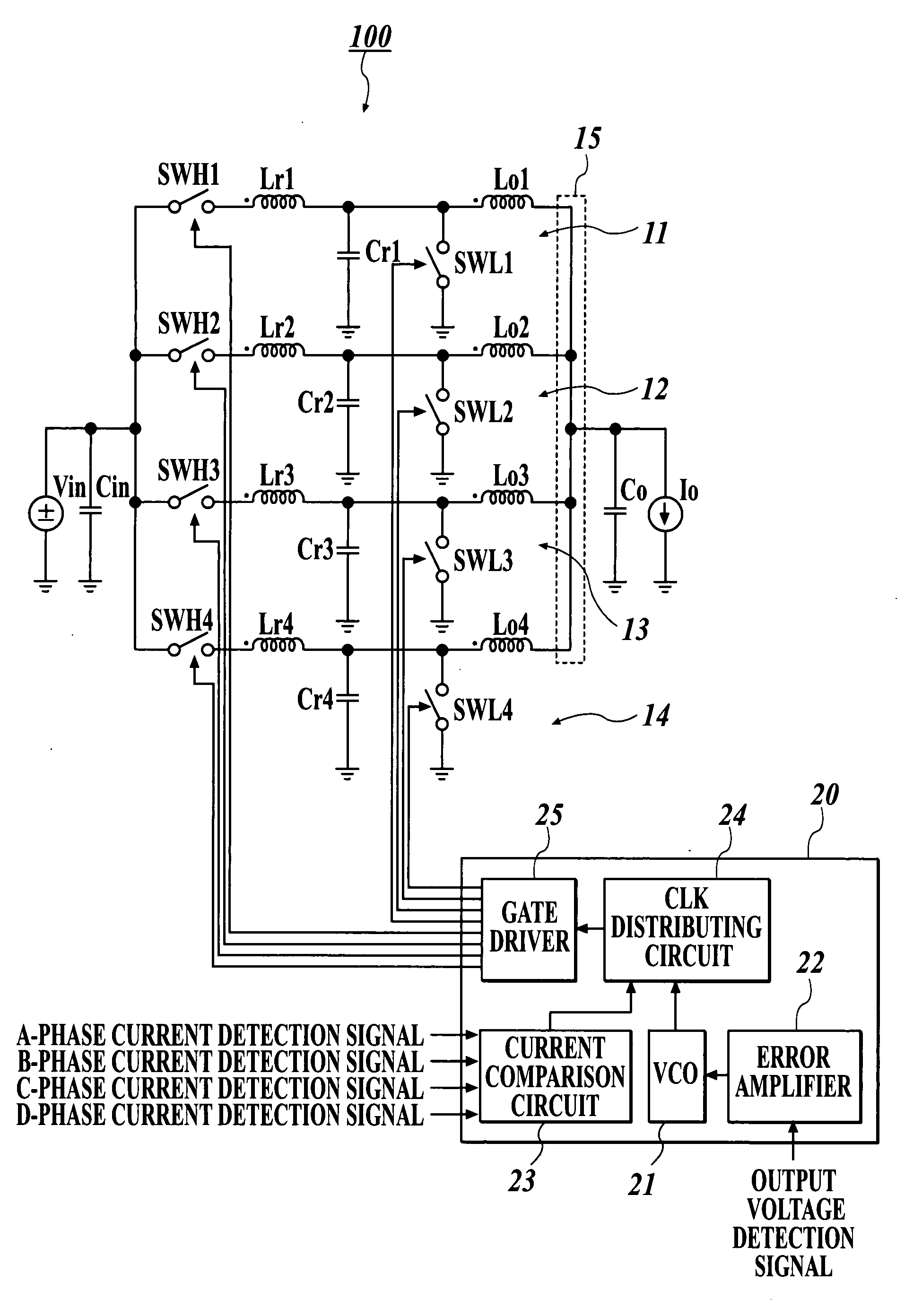
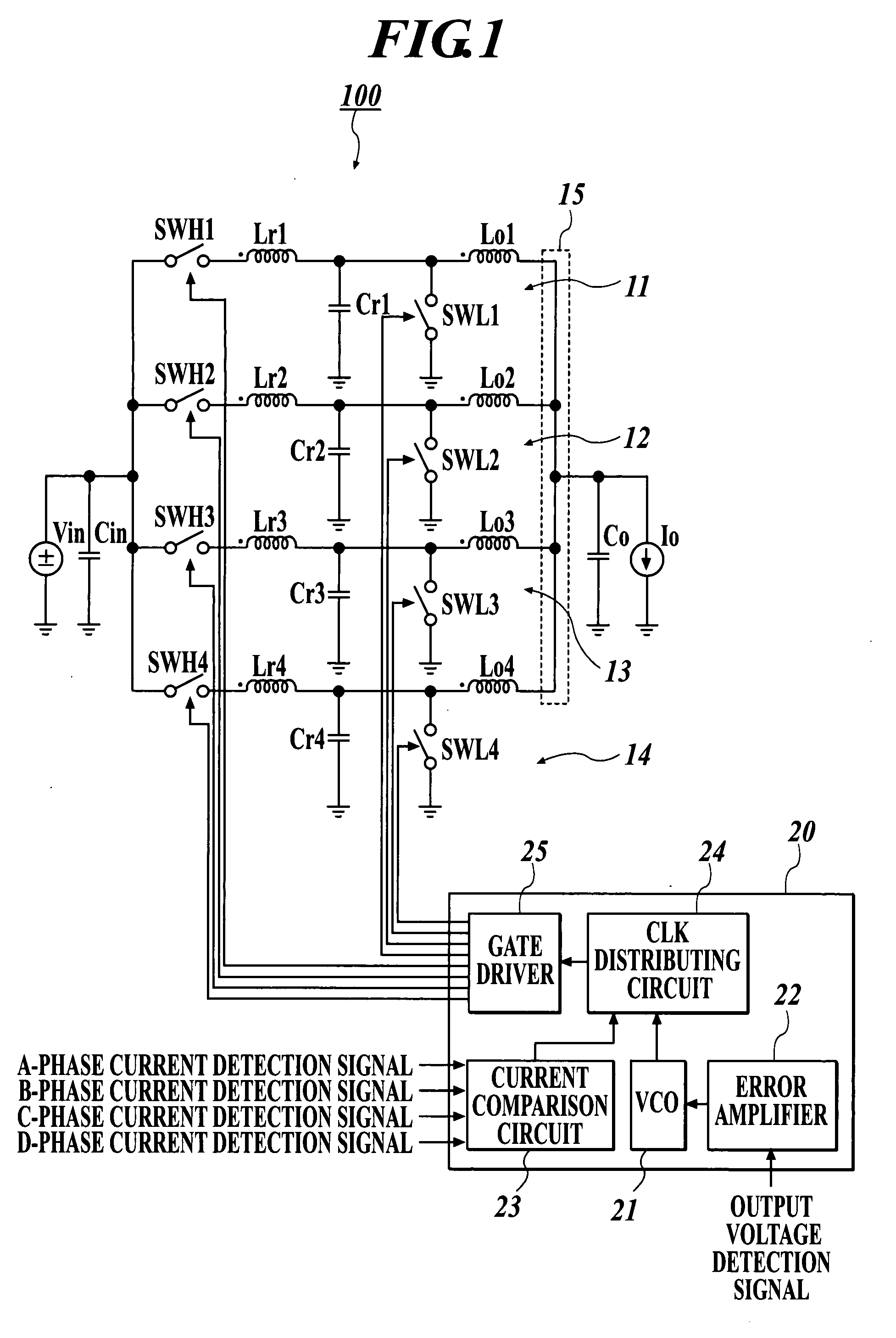
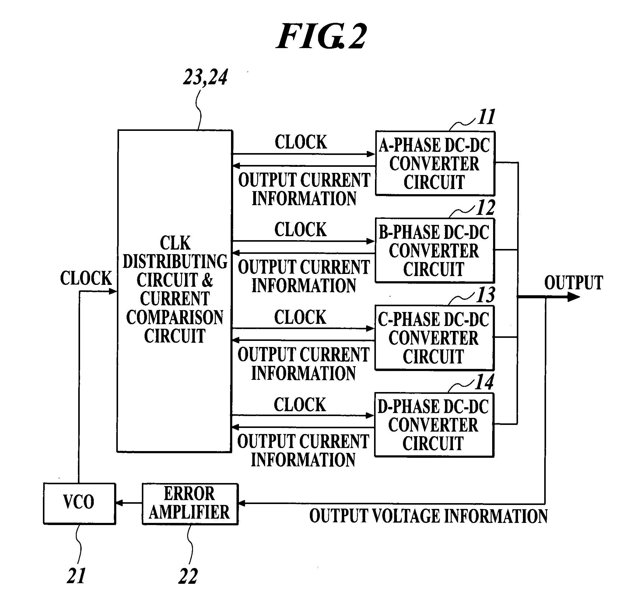
[0037]FIG. 1 is a configuration diagram showing a multiphase DC-DC converter according to a preferred embodiment of the present invention, and FIG. 2 is an explanatory diagram showing an overview of a control system configuration of the multiphase DC-DC converter.

[0038]A multiphase DC-DC converter 100 according to the embodiment includes a plurality of DC-DC converter circuits 11 to 14 arranged in parallel. The respective DC-DC converter circuits are operated so that output phases thereof are shifted to one another, and the respective outputs are added up to obtain one output. The plurality of DC-DC converter circuits 11 to 14 are successively denoted by A-phase to D-phase from the top.

[0039]The multiphase DC-DC converter 100 includes the DC-DC converter circuits 11 to 14 of A-phase to D-phase, a control block 20 to control the operation of these converter circuits, one...


PUM


Abstract

Disclosed is a multiphase DC-DC converter including a plurality of DC-DC converter circuits connected in parallel to one another; an output section to add up outputs of the plurality of DC-DC converter circuits to obtain one output; a timing generating circuit to generate timing signals for respectively operating the plurality of DC-DC converter circuits; a control circuit to selectively and sequentially operate the plurality of DC-DC converter circuits in synchronization with the timing signals outputted from the timing generating circuit so that output phases of the plurality of DC-DC converter circuits are different from one another; and a current detection circuit to detect an output current of each of the plurality of DC-DC converter circuits, wherein the control circuit selects one of the plurality of DC-DC converter circuit to be operated next based on an output of the current detection circuit.

Description

BACKGROUND OF THE INVENTION[0001]1. Field of the Invention[0002]The present invention relates to a multiphase DC-DC converter, and more particularly, to a useful technique which is applied to a multiphase DC-DC converter using a PFM (Pulse Frequency Modulation)-controlled DC-DC converter circuit.[0003]2. Description of Related Art[0004]There has been known a DC-DC converter of a multiphase system in which a plurality of DC-DC converter circuits are arranged in parallel and operated so that output phases of the respective DC-DC converter circuits are shifted to each other, and the respective outputs thereof are added up to obtain one output. According to such a multiphase DC-DC converter, a large output having a low ripple as a whole can be obtained.[0005]Japanese Patent Application Laid-Open Publication No. 2003-284333 discloses a DC-DC converter of a multiphase system in which PWM (Pulse Width Modulation)-controlled DC-DC converter circuits are arranged in parallel. Japanese Patent...

Claims


Application Information

Patent Timeline
IPC IPC(8): G05F1/44G05F1/10
CPCH02M3/1584
Inventor ENDO, NAOTOSHIMA, HITOSHI
Owner MITSUMI ELECTRIC CO LTD
Why Eureka
Try Eureka