
Element substrate, printhead, head cartridge, and printing apparatus

Inactive Publication Date: 2008-06-05
CANON KK
View PDF6 Cites 7 Cited by
  • Summary
  • Abstract
  • Description
  • Claims
  • Application Information

AI Technical Summary

Benefits of technology

[0016]It is an object of the present invention to provide a printhead element substrate which does not depend on a variation in heater driving voltage and can change the heater driving voltage without redesigning a printhead. It is another object of the present invention to provide a printhead element substrate which can prevent a printhead from breaking even when abnormality occurs in the power supply of a logical circuit.
[0032]The invention is particularly advantageous since it is possible to provide a printhead element substrate which does not depend on a variation in heater driving voltage and can change the heater driving voltage without redesigning a printhead.

Problems solved by technology

That is, it is difficult to make the voltage output from the driving voltage converter circuit match the driving voltage of the heaters.
On the other hand, when the power supply line for the voltage output from the driving voltage converter circuit is provided separately from the heater power supply voltage line, the cost of the entire system rises.
However, the driving voltage generating circuit of the prior art determines the output voltage VHTM in accordance with the voltage division ratio of the resistors and therefore has the following problems.
For this reason, it may be impossible to obtain desired discharge energy.
It is therefore impossible to employ the adjustment by changing the voltage VH.
If the power supply of the logical circuits causes a fault during, e.g., attachment / detachment or use of the printhead, the logical circuits may be unable to execute a normal operation.
For this reason, if the power supply of the logical circuits causes a fault when the voltage VH is being applied, the printhead may cause an operation error.

Method used


Image

  • Element substrate, printhead, head cartridge, and printing apparatus
  • Element substrate, printhead, head cartridge, and printing apparatus
  • Element substrate, printhead, head cartridge, and printing apparatus

Examples


Embodiment Construction

[0043]An embodiment of the present invention will be described next with reference to the accompanying drawings.

[0044]In this specification, the terms “print” and “printing” not only include the formation of significant information such as characters and graphics, but also broadly includes the formation of images, figures, patterns, and the like on a print medium, or the processing of the medium, regardless of whether they are significant or insignificant and whether they are so visualized as to be visually perceivable by humans.

[0045]Also, the term “print medium” not only includes a paper sheet used in common printing apparatuses, but also broadly includes materials, such as cloth, a plastic film, a metal plate, glass, ceramics, wood, and leather, capable of accepting ink.

[0046]Furthermore, the term “ink” (to be also referred to as a “liquid” hereinafter) should be extensively interpreted similar to the definition of “print” described above. That is, “ink” includes a liquid which, ...


PUM


Abstract

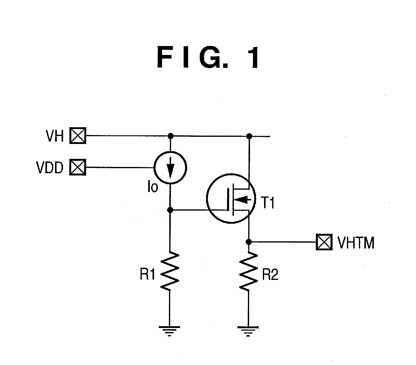
This element substrate is an element substrate for a printhead which includes a plurality of printing elements to which a first voltage is applied, a plurality of driving elements which drive the plurality of printing elements, a logical circuit which outputs a driving signal to control the plurality of driving elements, and a driving voltage converter circuit which converts the voltage of the driving signal output from the logical circuit into a second voltage lower than the first voltage and outputs the second voltage to the plurality of driving elements. The element substrate includes a driving voltage generating circuit which generates, on the basis of the first voltage, the second voltage to drive the driving voltage converter circuit. The driving voltage generating circuit has a constant current source for generating a constant current based on the first voltage and generates the second voltage based on the constant current.

Description

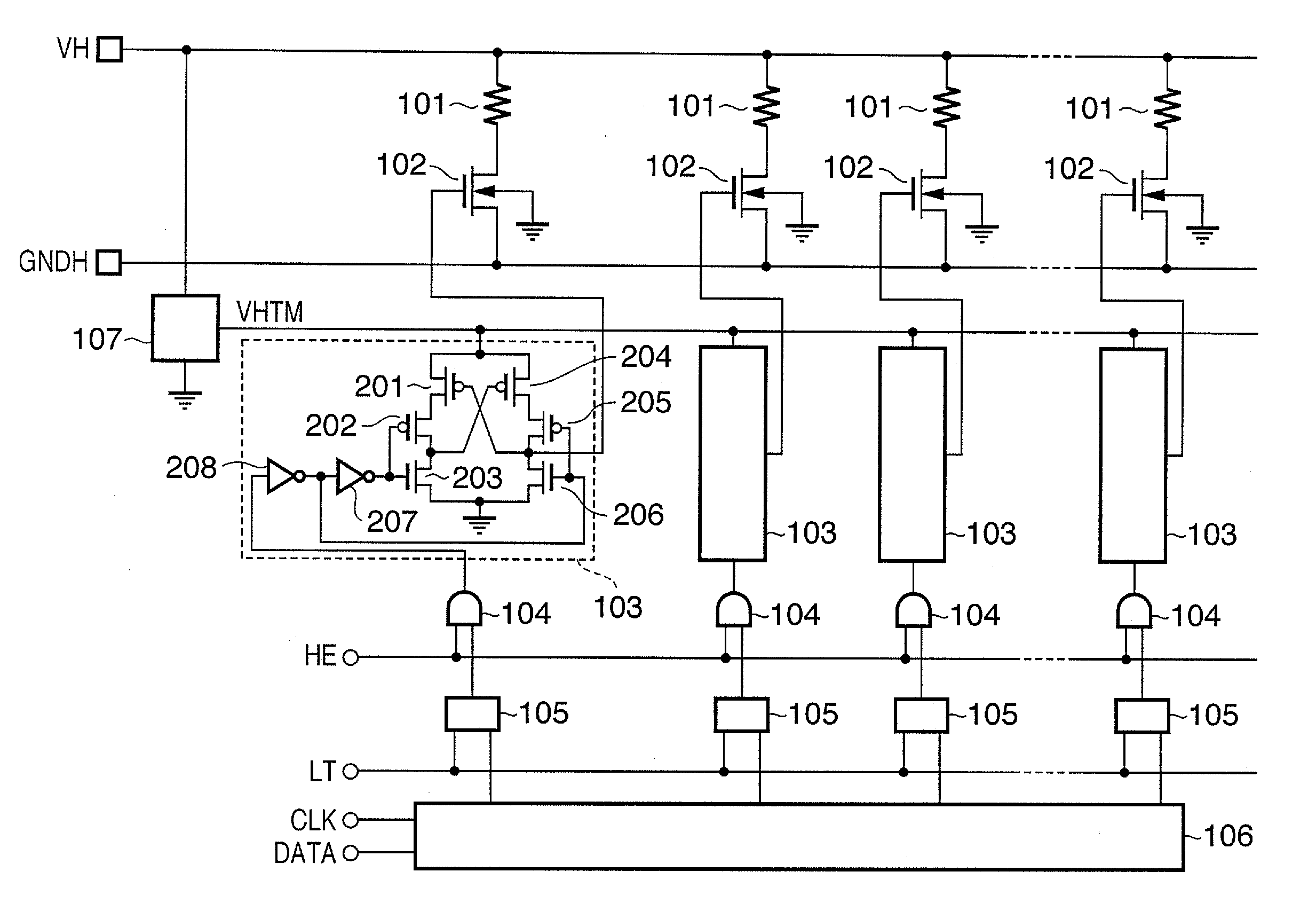
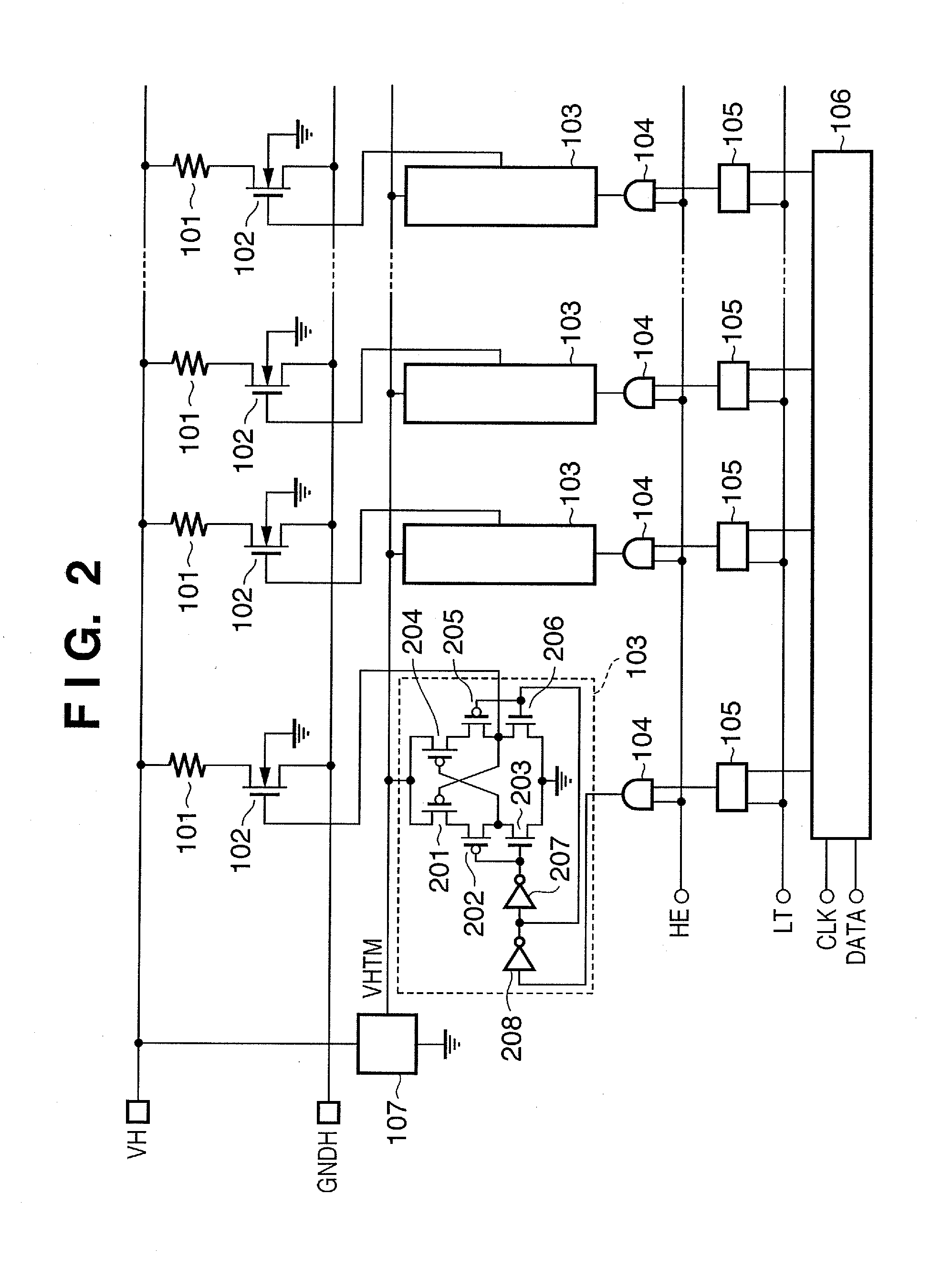
BACKGROUND OF THE INVENTION[0001]1. Field of the Invention[0002]The present invention relates to a printhead element substrate having a driving voltage generating circuit for driving a driving voltage converter circuit, a printhead, a head cartridge, and a printing apparatus.[0003]2. Description of the Related Art[0004]FIG. 2 shows the circuit arrangement of a conventional inkjet printhead. In a printhead of this type, the electrothermal transducers (heaters) and their driving circuits can be formed on a single substrate by using a semiconductor process technique, as described in, e.g., U.S. Pat. No. 6,290,334.[0005]Referring to FIG. 2, electrothermal transducers (heaters) 101 generate heat to discharge ink. N-type power transistors 102 supply a desired current to the heaters 101. A shift register 106 temporarily stores image data which determines whether to supply a current to the heaters 101 and discharge ink from the nozzles of the printhead. The shift register 106 has a transfer...

Claims


Application Information

Patent Timeline
IPC IPC(8): B41J2/14B41J2/05
CPCB41J2/04513B41J2/04541B41J2/0458B41J2/0455B41J2/04548
Inventor KUBO, KOUSUKEIMANAKA, YOSHIYUKIHATSUI, TAKUYATAKEUCHI, SOUTAYAMAGUCHI, TAKAAKIMATSUI, TAKAHIRO
Owner CANON KK
Learn More