However, there are limitations and drawbacks to gimbaled PTZ cameras.
The limitations include: loss of viewing angle as a camera is zoomed on a target; the control, mechanical, and reliability issues associated with being able to pan and tilt a camera; and cost and complexity issues associated with a multi-camera gimbaled
system.
The first limitation is the ability of the camera to
zoom while still providing a wide surveillance coverage.
This makes detection, classification and interrogation of targets much more difficult or altogether impossible while surveilling a
wide area.
The tradeoff for optically zooming a camera for increased spatial resolution is the loss of coverage area.
Thus, a conventional camera using an optical
zoom does not provide
wide area coverage while providing increased spacial resolution of a target area.
Currently, there is not a
single point solution that provides both
wide area surveillance and high-resolution target interrogation.
There are also limitations and drawbacks associated with surveillance cameras using gimbaled pan and tilt actuations for scanning a target area or tracking a target.
While these techniques are effective at extending the area of coverage of one camera, the camera can only surveil one section of a total area of interest at any one time, and is blind to regions outside the field-of-view.
For surveillance applications, this approach leaves the surveillance
system vulnerable to missing events that occur when the camera field-of-view is elsewhere.
A further limitation of the current state-of-the-art surveillance cameras arises when actively tracking a target with a conventional “Pan, Tilt, and
Zoom” (PTZ) camera.
This method presents several challenges to automated video understanding algorithms.
Secondly, the complexity that is intrinsic to such an opto-
mechanical system, with associated motors, actuators, gimbals, bearings and such, increases the size and cost of the
system.
Further, the Mean Time Between Failure (MTBF) is detrimentally impacted by the increased complexity, and number of high performance
moving parts.
However, there are several limitations to this approach.
First, there is no improvement to detection range since detection is achieved with fixed point cameras, presumably set to wide
area coverage.
Second, the PTZ channel can only interrogate one target at a time, which requires complete attention of operator, at the expense of the rest of the FOV covered by the other cameras.
This leaves the area under surveillance vulnerable to events and targets not detected.
However, this solution has the
disadvantage of being difficult to set up as alignment is critical between fixed and PTZ cameras.
True bore-sighting is difficult to achieve in practice, and the unavoidable displacement between fixed and PTZ video views introduce viewing errors that are cumbersome to correct.
Mapping each field-of-view through GPS or Look Up Tables (LUTS) is complex and lacks stability; any change to any camera location requires re-calibration, ideally to sub-pixel accuracy.


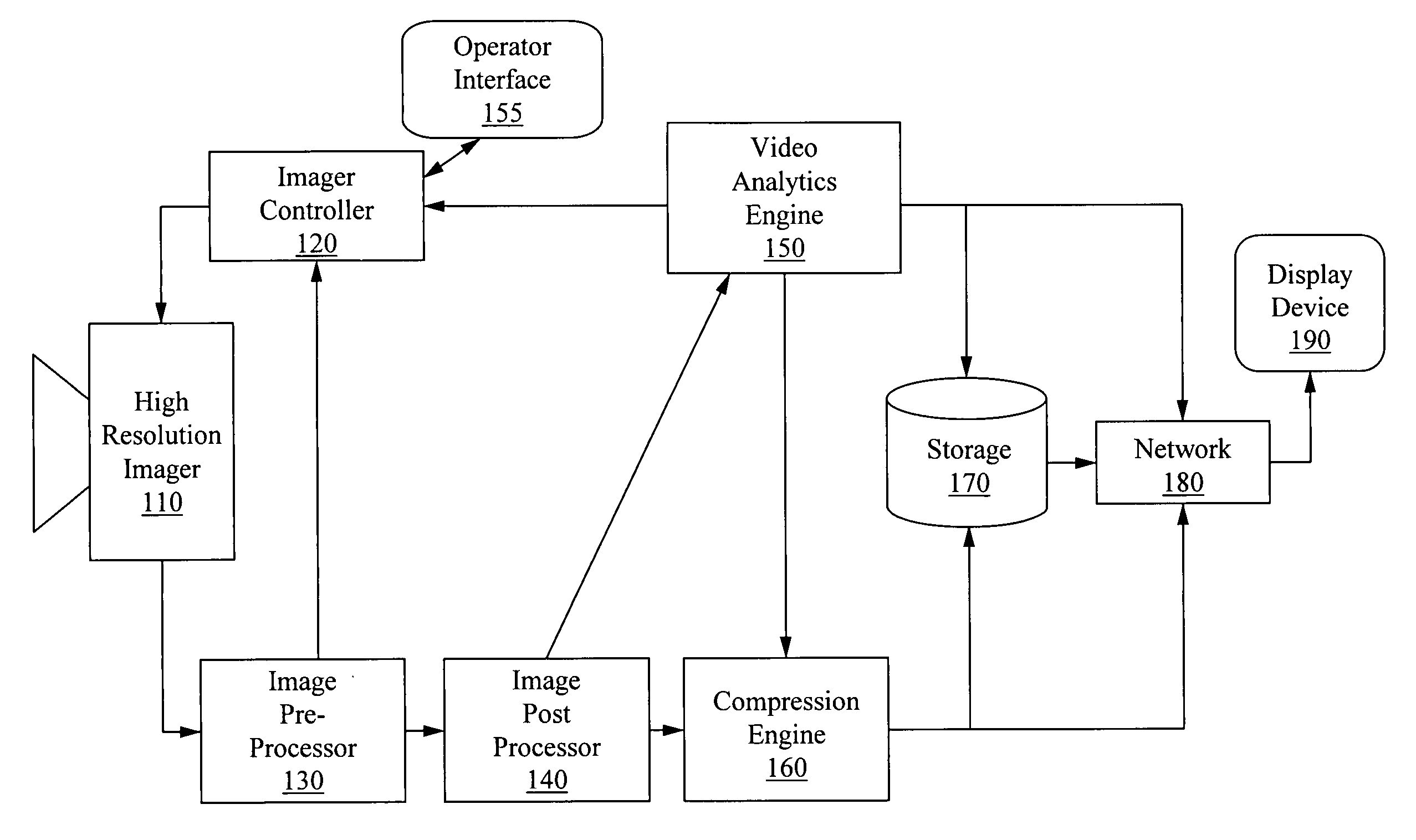
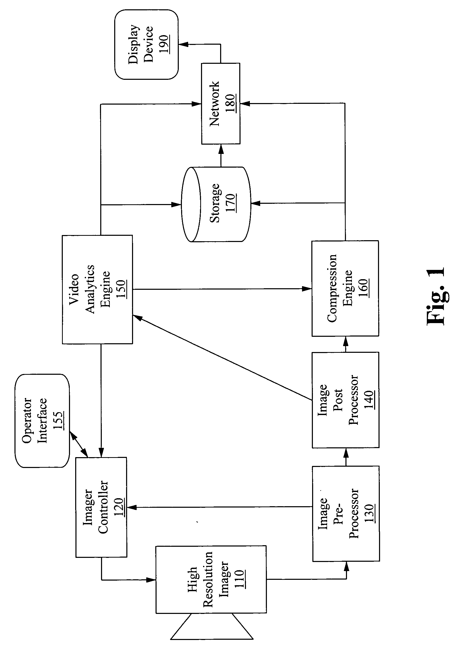
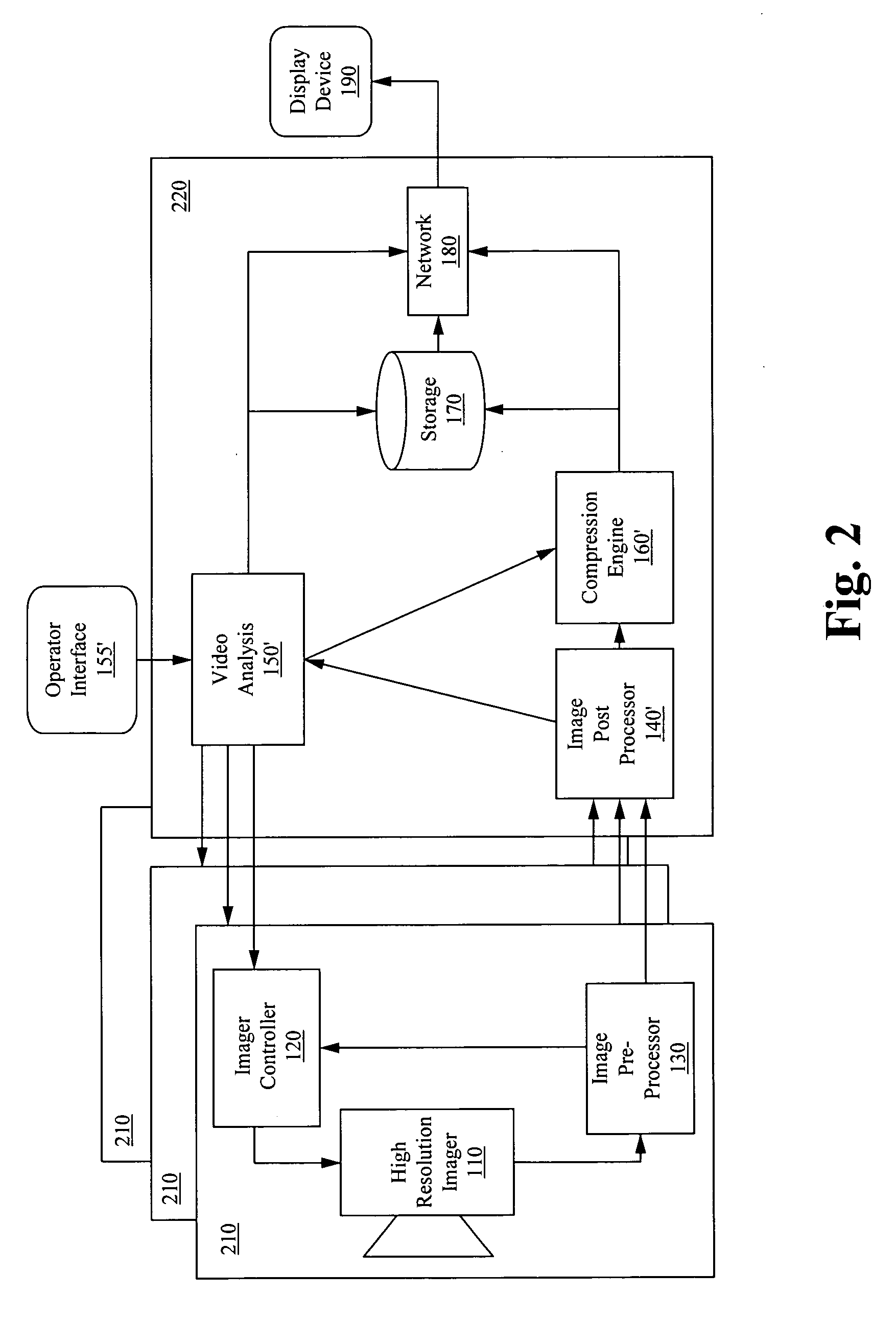