Circuit protection device

a protection device and circuit technology, applied in the direction of emergency protection arrangements for limiting excess voltage/current, spark gaps, electrical equipment, etc., can solve the problems of movs continuing to overheat, unable to protect against major over-voltage conditions, and unable to solve major over-voltage conditions

Active Publication Date: 2008-06-05
FERRAZ SHAWMUT
View PDF45 Cites 45 Cited by
  • Summary
  • Abstract
  • Description
  • Claims
  • Application Information

AI Technical Summary

Benefits of technology

[0010]It is an object of the present invention to provide a circuit protection device to protect sensitive circuit components and systems from current and voltage surges.
[0011]It is another object of the present invention to provide a circuit protection device as described above to prevent catastrophic failure of a transient voltage surge suppression (TVSS) system within a circuit that may occur from repetitive circuit faults or from a single fault of excessive proportion.
[0015]A still further object of the present invention is to provide a circuit protection device as described above that is modular in design and easily replaceable in a circuit.

Problems solved by technology

In this respect, such systems are designed to suppress relatively minor fault conditions, but are not designed to protect against major over-voltage conditions.
Such major over-voltage conditions can have catastrophic effects on sensitive electronic circuits and components.
If an over-voltage condition is not discontinued, the MOVs will continue to overheat and can ultimately fail catastrophically, i.e., rupture or explode.
Such catastrophic failure may destroy the sensitive electronic equipment and components in the vicinity of the MOVs.
The destruction of electrical equipment or components in the electrical distribution system can disrupt power to buildings or floors for prolonged periods of time until such components are replaced or repaired.
Moreover, the failure of the MOVs in a surge suppression system may allow the fault condition to reach the sensitive electronic equipment the system was designed to protect.
This condition has the potential to stress the solder joints leading to premature wear out or failure.

Method used


Image

  • Circuit protection device
  • Circuit protection device
  • Circuit protection device

Examples


Embodiment Construction

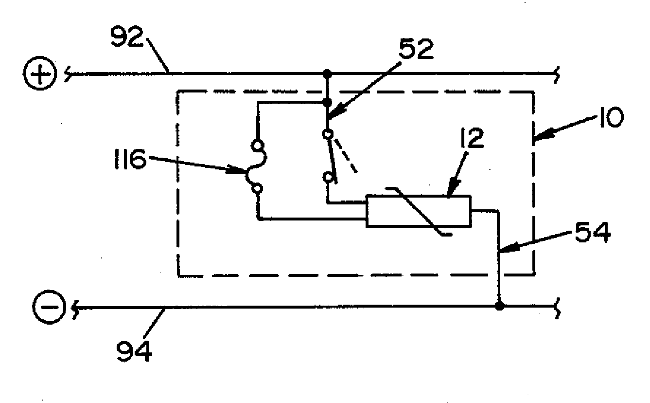
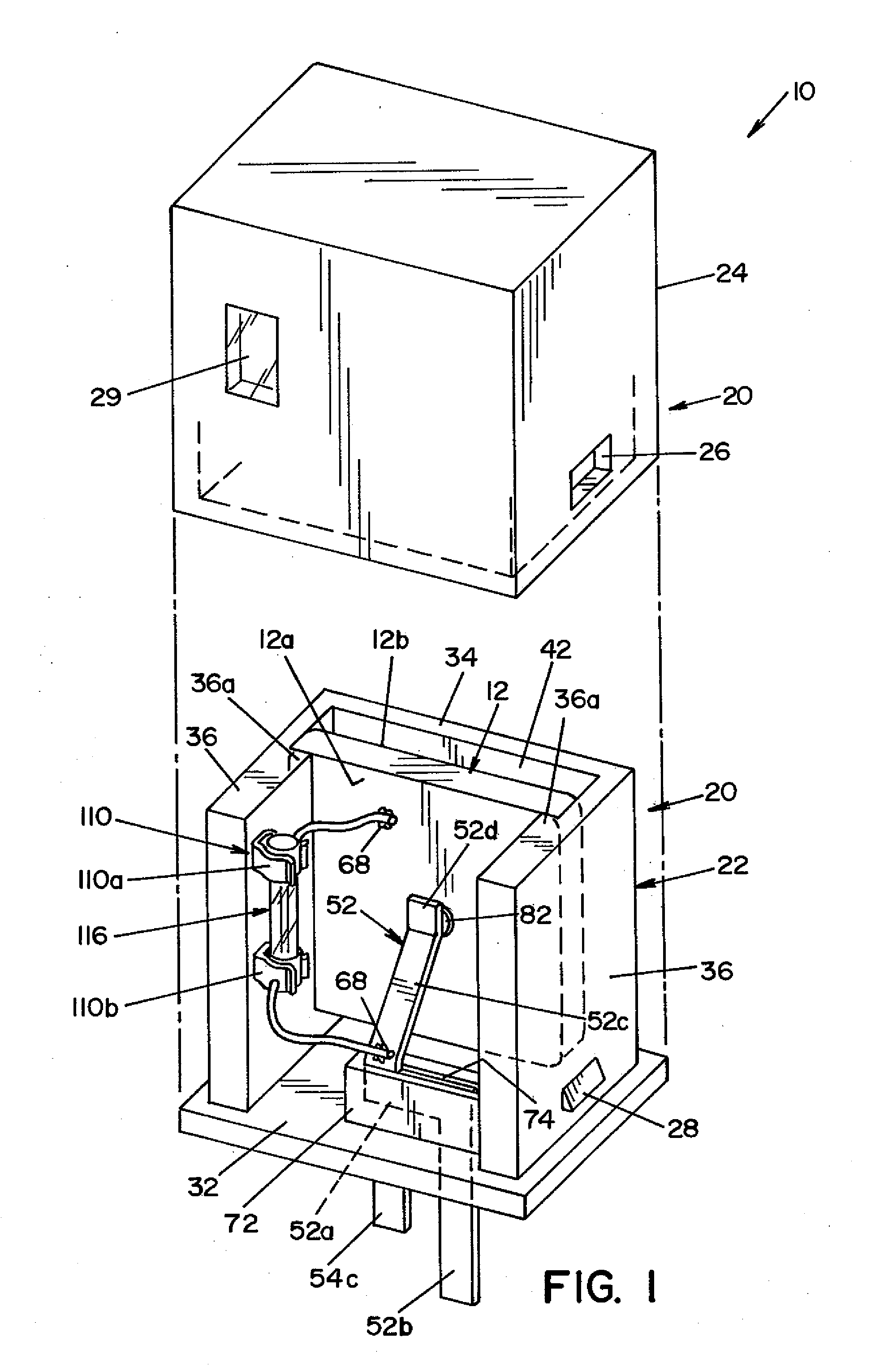
[0025]Referring now to the drawings wherein the showings are for the purpose of illustrating a preferred embodiment of the invention only, and not for the purpose of limiting same, FIG. 1 is an exploded perspective view of a transient voltage suppression device 10 for use with a power distribution system for preventing voltage fault conditions from reaching a sensitive circuit load.

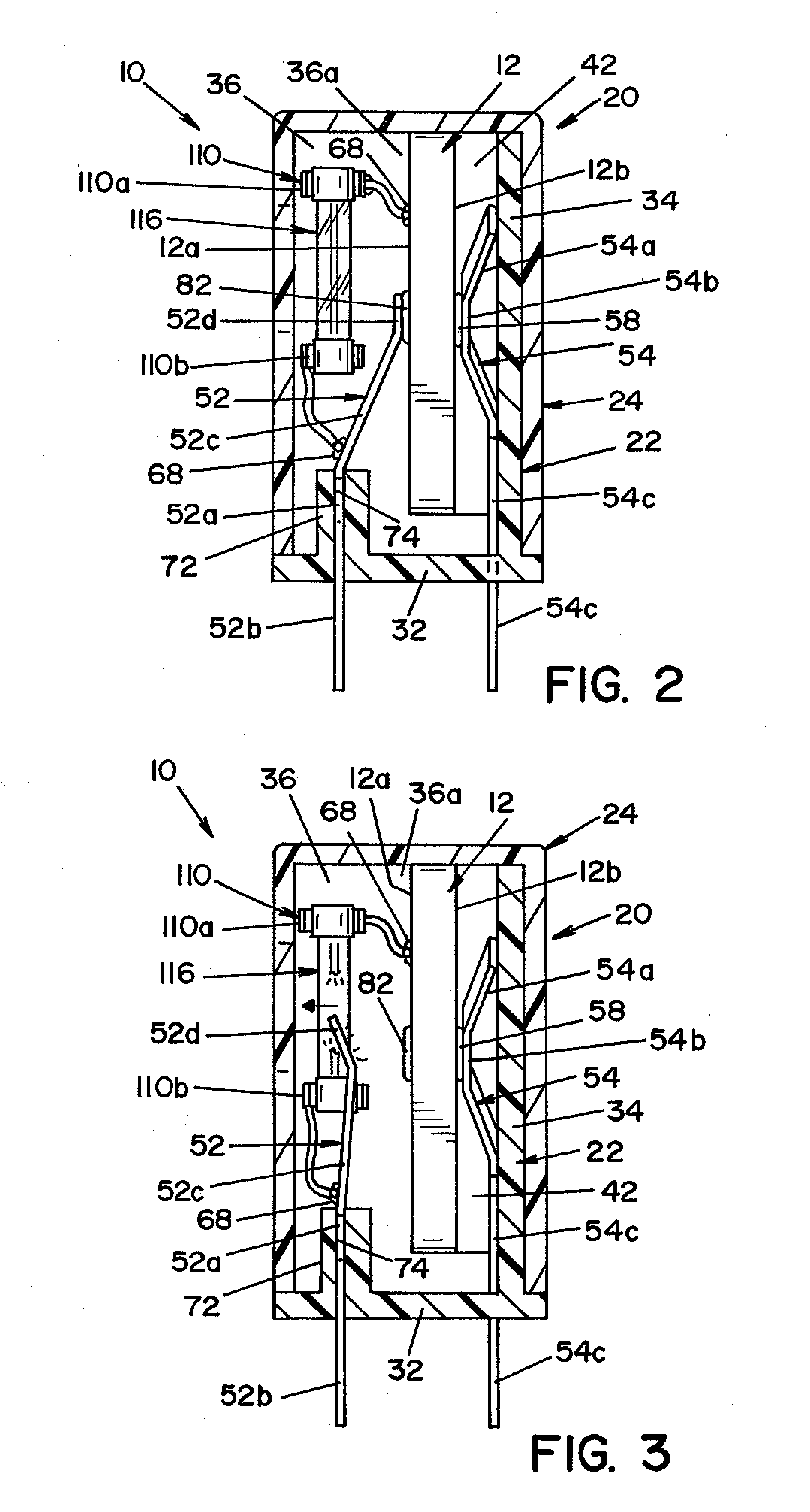
[0026]Voltage suppression device 10 is generally comprised of a voltage sensitive element 12 that is contained within a housing 20. Housing 20 is comprised of a base section 22 and a cover section 24. Base section 22 is adapted to receive and hold the operative elements of a voltage suppression device 10. To this end, base section 22 includes a generally planar bottom wall portion 32. A generally U-shaped structure, comprised of a back wall 34 and opposed side walls 36, extends from bottom wall 32. Each side wall 36 includes an inward extending wall section 36a that is spaced from back wall 34. Side walls...


PUM


Abstract

A voltage suppression device for suppressing voltage surges in an electrical circuit, comprised of a voltage sensitive element having a predetermined voltage rating, the voltage sensitive element increasing in temperature as voltage applied across the voltage sensitive element exceeds the voltage rating. Terminals are provided for electrically connecting the voltage sensitive element between a power line of an electrical circuit and a ground or neutral line of the electrical circuit. A normally closed, thermal switch is electrically connected in series with the voltage sensitive element between one line of the electrical circuit and the voltage sensitive element, the thermal switch being thermally coupled to the voltage sensitive element wherein the thermal switch moves from a normally closed position to an open position to form a gap between the thermal switch and the voltage sensitive element when the temperature of the voltage sensitive element reaches a level indicating an over-voltage condition. When the thermal switch moves to the open position, residual follow on current is shunted by a fuse element connected in parallel with the thermal switch. Current flows through the fuse element until the fuse element melts. Electrical arcing is contained inside the fuse until extinguished.

Description

FIELD OF THE INVENTION [0001]The present invention relates generally to circuit protection devices, and more particularly to a device that suppresses transient current / voltage surges.BACKGROUND OF THE INVENTION [0002]Many of today's highly sensitive electronic components, such as computer and computer-related equipment, that are used in commercial and residential applications contain transient voltage surge suppression (TVSS) devices. These devices protect sensitive and / or expensive electronic circuits and components from damage from over-voltage fault conditions. Such transient voltage surge suppression systems are typically designed for moderate fault conditions expected in normal use. In this respect, such systems are designed to suppress relatively minor fault conditions, but are not designed to protect against major over-voltage conditions. Examples of major over-voltage conditions include those that may occur from losing the system neutral or ground termination, or from repeti...

Claims


Application Information

Patent Timeline
Patent Type & Authority Applications(United States)
IPC IPC(8): H02H9/04
CPCH01C7/112H02H9/042H01T1/14
Inventor DE PALMA, JEAN-FRANCOISMOSESIAN, JERRY L.
Owner FERRAZ SHAWMUT
Why Eureka
Try Eureka