Circuit protection device

a protection device and circuit technology, applied in the direction of circuit arrangement, emergency protection arrangement for limiting excess voltage/current, spark gap details, etc., can solve the problems of catastrophic failure of sensitive electronic circuits and components, inability to protect against major over-voltage conditions, and movs will continue to overheat, so as to achieve the effect of convenient replacement in the circuit lin

Inactive Publication Date: 2013-10-10
MERSEN USA NEWBURYPORT MA
View PDF1 Cites 5 Cited by
  • Summary
  • Abstract
  • Description
  • Claims
  • Application Information

AI Technical Summary

Benefits of technology

[0011]It is an advantage of the present invention to provide a circuit protection device to protect sensitive circuit components and systems from current and voltage surges.
[0012]It is another advantage of the present invention to provide a circuit protection device as described above to prevent catastrophic failure of a transient voltage surge suppression (TVSS) system within a circuit that may occur from repetitive circuit faults or from a single fault of excessive proportion.
[0013]A further advantage of the present invention is to provide a circuit protection device as described above that includes a current suppression device and a voltage suppression device.
[0014]Another advantage of the present invention is to provide a circuit protection device as described above for protecting a transient voltage surge suppression system having metal-oxide varistors (MOVs).
[0015]A still further advantage of the present invention is to provide a circuit protection device as described above that includes a metal-oxide varistor as a circuit-breaking device.
[0016]A still further advantage of the present invention is to provide a circuit protection device as described above that is modular in design and easily replaceable in a circuit line.

Problems solved by technology

In this respect, such systems are designed to suppress relatively minor fault conditions, but are not designed to protect against major over-voltage conditions.
Such major over-voltage conditions can have catastrophic effects on sensitive electronic circuits and components.
If an over-voltage condition is not discontinued, the MOVs will continue to overheat and can ultimately fail catastrophically, i.e., rupture or explode.
Such catastrophic failure may destroy the sensitive electronic equipment and components in the vicinity of the MOVs.
The destruction of electrical equipment or components in the electrical distribution system can disrupt power to buildings or floors for prolonged periods of time until such components are replaced or repaired.
Moreover, the failure of the MOVs in a surge suppression system may allow the fault condition to reach the sensitive electronic equipment the system was designed to protect.

Method used


Image

  • Circuit protection device
  • Circuit protection device
  • Circuit protection device

Examples


Embodiment Construction

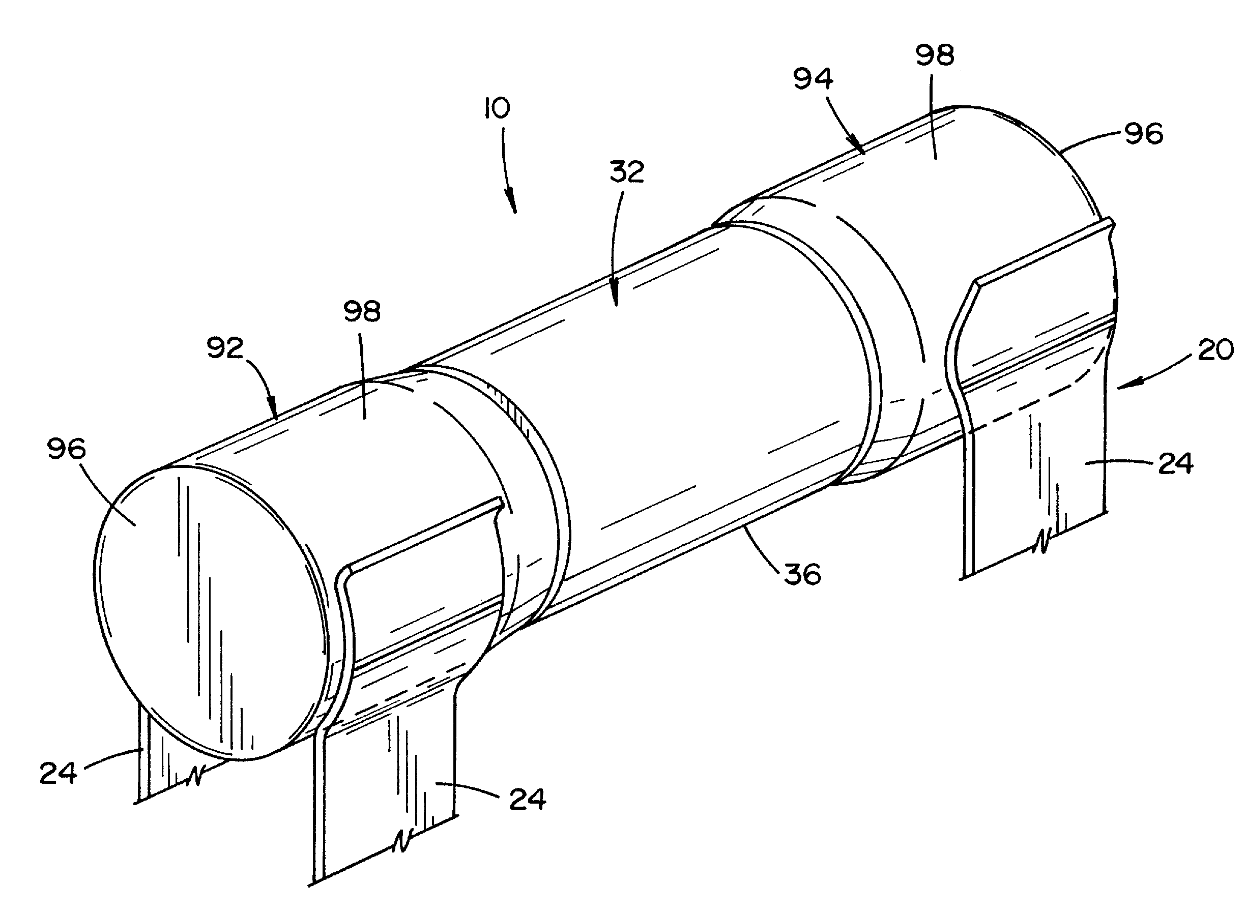
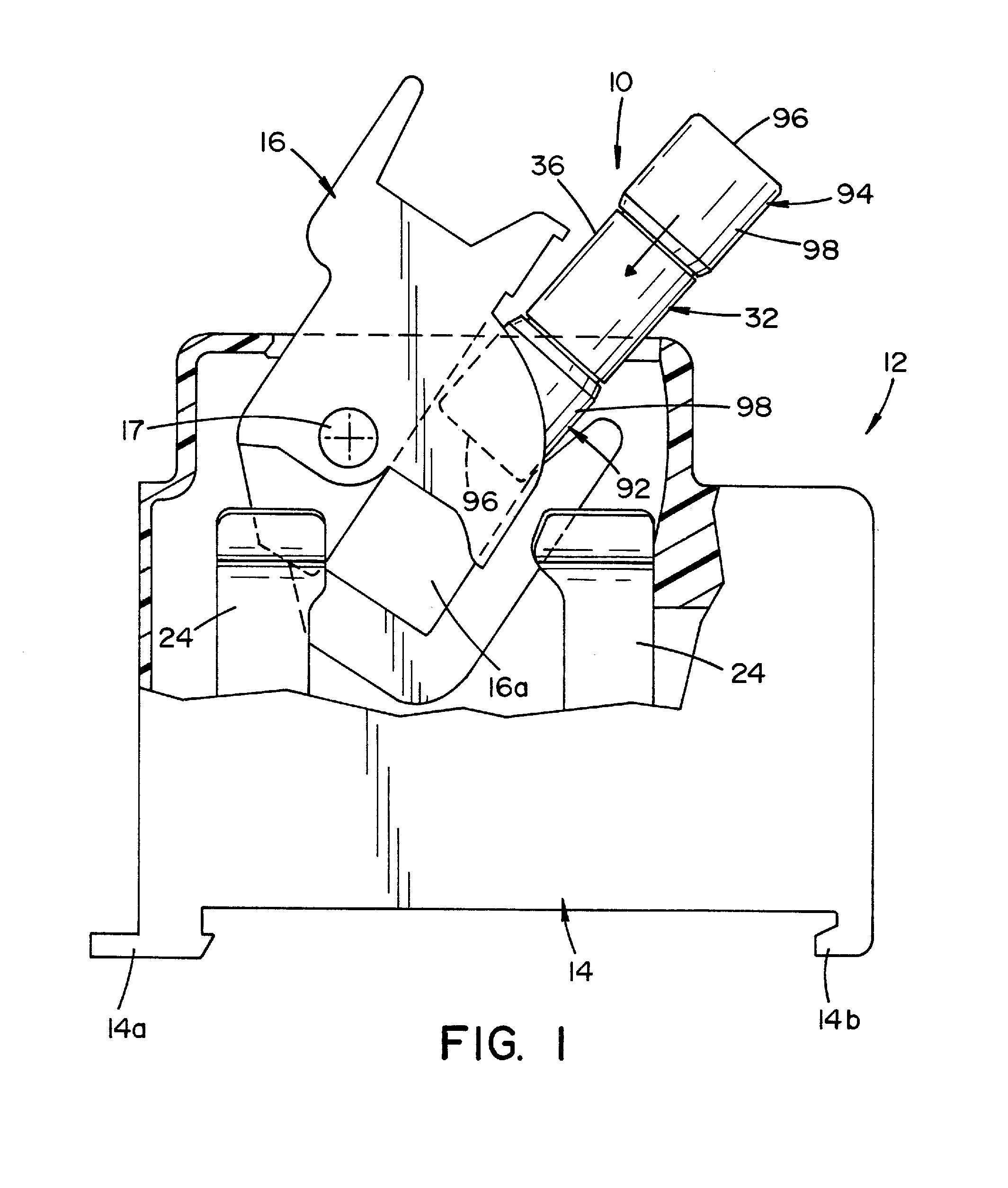
[0033]Referring now to the drawings wherein the showings are for the purpose of illustrating a preferred embodiment of the invention only and not for the purpose of limiting same, FIG. 1 shows a circuit protection device 10, according to a preferred embodiment of the present invention, within a conventional, fuse holder 12. Fuse holder 12, in and of itself, forms no part of the present invention, but shall be described briefly to illustrate a preferred manner of use of a circuit protection device 10.

[0034]Fuse holder 12 is comprised of a molded, polymer housing 14 having leg portion 14a, 14b formed along the lower surface thereof. Leg portion 14a, 14b are designed to allow housing 14 to be attached, in snap-lock fashion to a mounting rail (not shown), wherein spaced-apart leads (not shown) that form part of an electrical circuit come into electrical contact with spaced-apart pairs of contact blades 24. A receiver 16 is pivotally mounted to housing 14 by a pin 17. Receiver 16 include...


PUM


Abstract

A voltage suppression device for suppressing voltage surges in an electrical circuit having a voltage sensitive assembly comprised of a plurality of tubular sections within a tubular casing.

Description

FIELD OF THE INVENTION[0001]The present invention relates generally to circuit protection devices and, more particularly, to a device that suppresses transient current / voltage surges.BACKGROUND OF THE INVENTION[0002]Many of today's highly sensitive electronic components, such as computer and computer-related equipment that are used in commercial and residential applications contain transient voltage surge suppression (TVSS) devices. These devices protect sensitive and / or expensive electronic circuits and components from damage from over-voltage fault conditions. Such transient voltage surge suppression systems are typically designed for moderate fault conditions expected in normal use. In this respect, such systems are designed to suppress relatively minor fault conditions, but are not designed to protect against major over-voltage conditions. Examples of major over-voltage conditions include those that may occur from losing the system neutral or ground termination, or from repetiti...

Claims


Application Information

Patent Timeline
Patent Type & Authority Applications(United States)
IPC IPC(8): H02H9/04
CPCH02H9/041H01C7/126H01T1/14
Inventor MOSESIAN, JERRY L.DE PALMA, JEAN-FRANCOISRADZIM, MARK A.
Owner MERSEN USA NEWBURYPORT MA
Why Eureka
Try Eureka