
Low Capacity Sodium Hypochlorite Generation System

a sodium hypochlorite and generation system technology, applied in the field of low capacity systems, can solve the problems of not being suited to low capacity situations, high maintenance costs, and inconvenient to operate, and achieve the effects of cost saving, cost saving, and reduced chemical costs

Inactive Publication Date: 2014-11-13
CABRERA MARIO D
View PDF4 Cites 4 Cited by
  • Summary
  • Abstract
  • Description
  • Claims
  • Application Information

AI Technical Summary

Benefits of technology

The Low Capacity Sodium Hypochlorite Generator (LCHG) system offers a cost-effective alternative to conventional sodium hypochlorite pump feed systems commonly used in water treatment disinfection. By using common salt to generate a 0.6% to 1.0% sodium hypochlorite solution, instead of higher cost commercial 12 to 15% sodium hypochlorite, cost savings are realized. Additionally, since less than 1% sodium hypochlorite is considered non-hazardous, no special handling or containment is required, which is not the case for conventional 12 to 15% sodium hypochlorite. The LCHG system utilizes batching instead of the conventional continuous flow through method, which eliminates brine and dilution water metering pumps, their associated controls, and required maintenance / servicing. Batching also precisely meters the amount of brine to dilution water in the reaction chamber (electrolyzer) to produce a consistent strength solution. This results in a system with less components, higher reliability, modular design, simpler to maintain and simpler to trouble shot / repair. When integrated with a dosing pump and its associated hardware, LCHG forms a complete water treatment disinfection system.

Problems solved by technology

The expense and hazards of transporting bulk chlorine has led to the development of on-site electrolytic generation systems, which electrolyze an aqueous solution of sodium chloride to produce sodium hypochlorite.
While the continuous flow electrolytic chlorination systems work well in high volume, high capacity applications, they are not well suited to low capacity situations.
This is because the precise control of flow rates at very low volumes requires specialized pumps, which are expensive and costly to maintain.

Method used


Image

  • Low Capacity Sodium Hypochlorite Generation System
  • Low Capacity Sodium Hypochlorite Generation System

Examples


Embodiment Construction

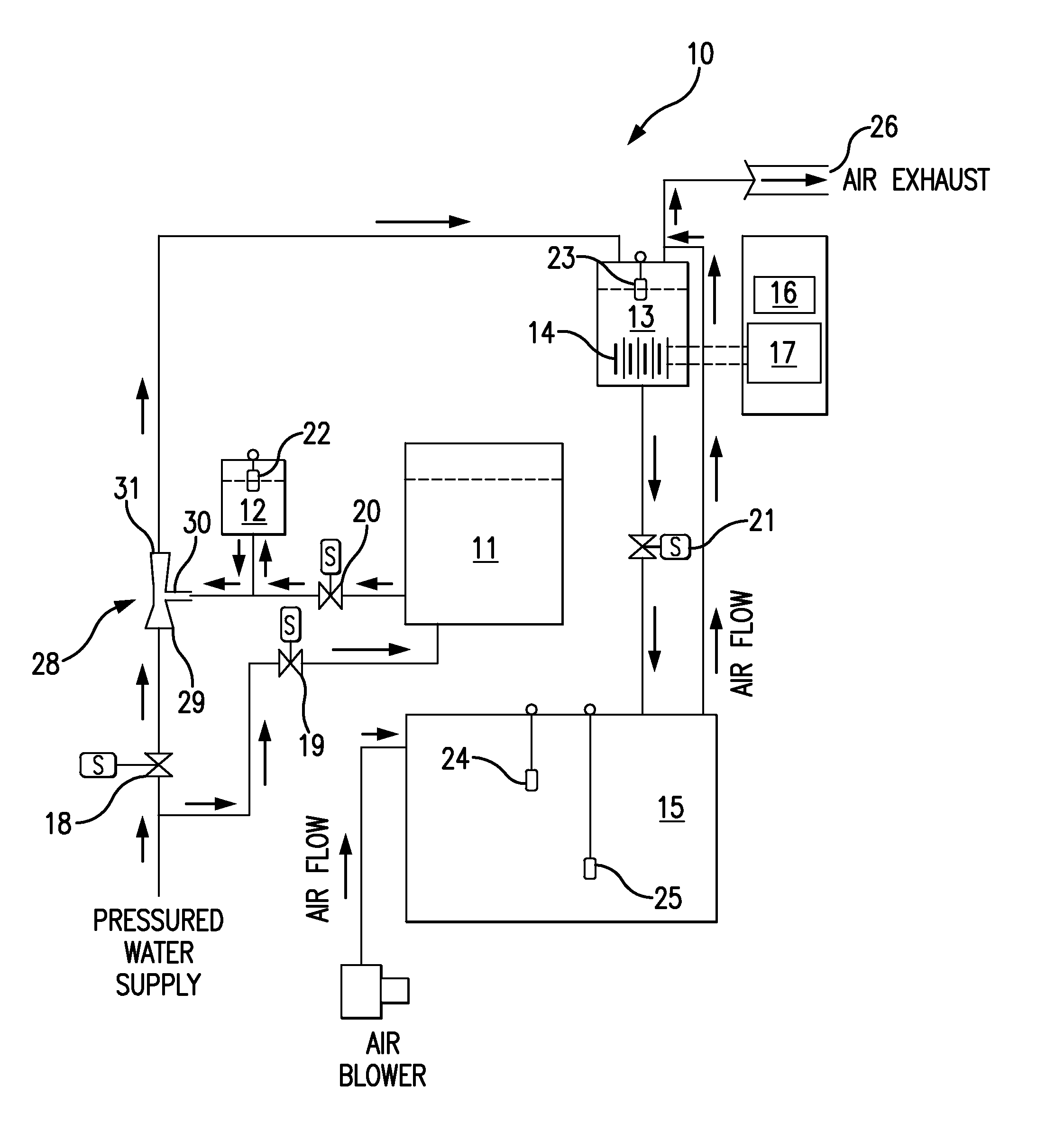
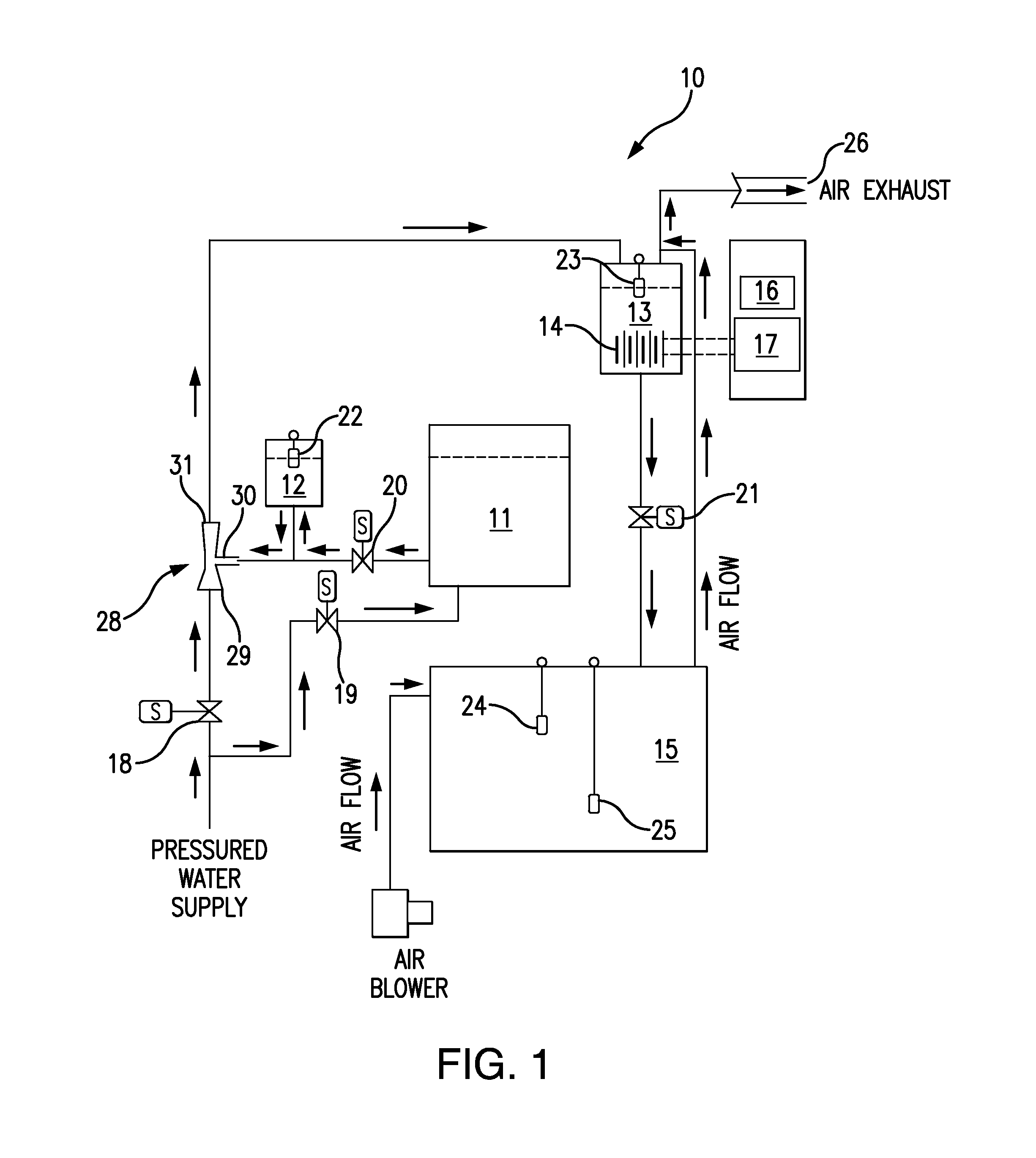
[0011]Referring to FIG. 1, the LCHG system 10 has a series of process tanks, comprising a salt saturator tank 11, a brine batch tank 12, a reactor tank 13, an electrolytic unit 14 within the reactor tank 13, and a product tank 15. The electrolytic unit 14 preferably consists of a series of undivided monopolar electrolytic cells that are externally electrically interconnected.

[0012]Controlling the sequence of LCHG operations is a programmable logic controller (PLC) 16. Electrical power to energize the electrolytic unit 14 is provided by a power supply 17.

[0013]The process tanks are hydraulically interconnected, with a series of solenoid valves, 18, 19, 20 and 21, controlling the flow between the tanks Filling of the tanks is regulated by float switches, 22, 23, 24 and 25. A blower 26 is provided to vent hydrogen gas generated by the electrolytic unit 14. A water source 27 furnishes a pressurized flow of water, which can be directed either to the saturation tank 11 or to an eductor 28...


PUM

PropertyMeasurementUnit
Fractionaaaaaaaaaa
Fractionaaaaaaaaaa
Concentrationaaaaaaaaaa

Abstract

A Low Capacity Sodium Hypochlorite Generation (LCHG) system uses batching rather than the conventional continuous flow method in the production of sodium hypochlorite. Batching eliminates the need for metering pumps for brine and dilution water, as well as their associated controls and maintenance / servicing demands. Batching also precisely controls the ratio of brine to dilution water in the electrolyzer to produce a consistent strength sodium hypochlorite solution. Consequently, the LCHG system has fewer components, greater reliability and simpler maintenance than the continuous-flow on-site electrolytic chlorination systems.

Description

BACKGROUND OF THE INVENTION[0001]The present invention relates to the field of devices and methods for generating an aqueous solution of sodium hypochlorite by electrolysis of an aqueous salt solution. More particularly, the present invention relates to a low capacity system for generating for electrolytic generation of sodium hypochlorite.[0002]Chlorination has been the standard method of disinfecting water supplies, potable water and swimming pools for over a century. The expense and hazards of transporting bulk chlorine has led to the development of on-site electrolytic generation systems, which electrolyze an aqueous solution of sodium chloride to produce sodium hypochlorite. Examples of such systems are disclosed in the Scoville (U.S. Pat. No. 4,329,215) and Bess et al. (U.S. Pat. No. 6,805,787), which disclosures are incorporated herein by reference. These electrolytic chlorination systems utilize a continuous flow process, wherein pumps are used to move the brine and water in...

Claims


Application Information

Patent Timeline
IPC IPC(8): C02F1/467
CPCC02F1/4674C02F1/46104C02F2201/46145C02F2201/4618C02F2209/005C02F2209/42
Inventor CABRERA, MARIO D.
Owner CABRERA MARIO D
Learn More