
Vehicular illumination system

a technology of illumination system and vehicle, which is applied in the direction of lighting and heating apparatus, instruments, lighting support devices, etc., can solve problems such as control delay, and achieve excellent action and effect, reduce processing load, and curtail control delay

Inactive Publication Date: 2008-06-05
TOYOTA JIDOSHA KK
View PDF4 Cites 64 Cited by
  • Summary
  • Abstract
  • Description
  • Claims
  • Application Information

AI Technical Summary

Benefits of technology

[0008]The present invention has been made in view of these circumstances, and it is an object thereof to reduce the processing load and curb control delay.

Problems solved by technology

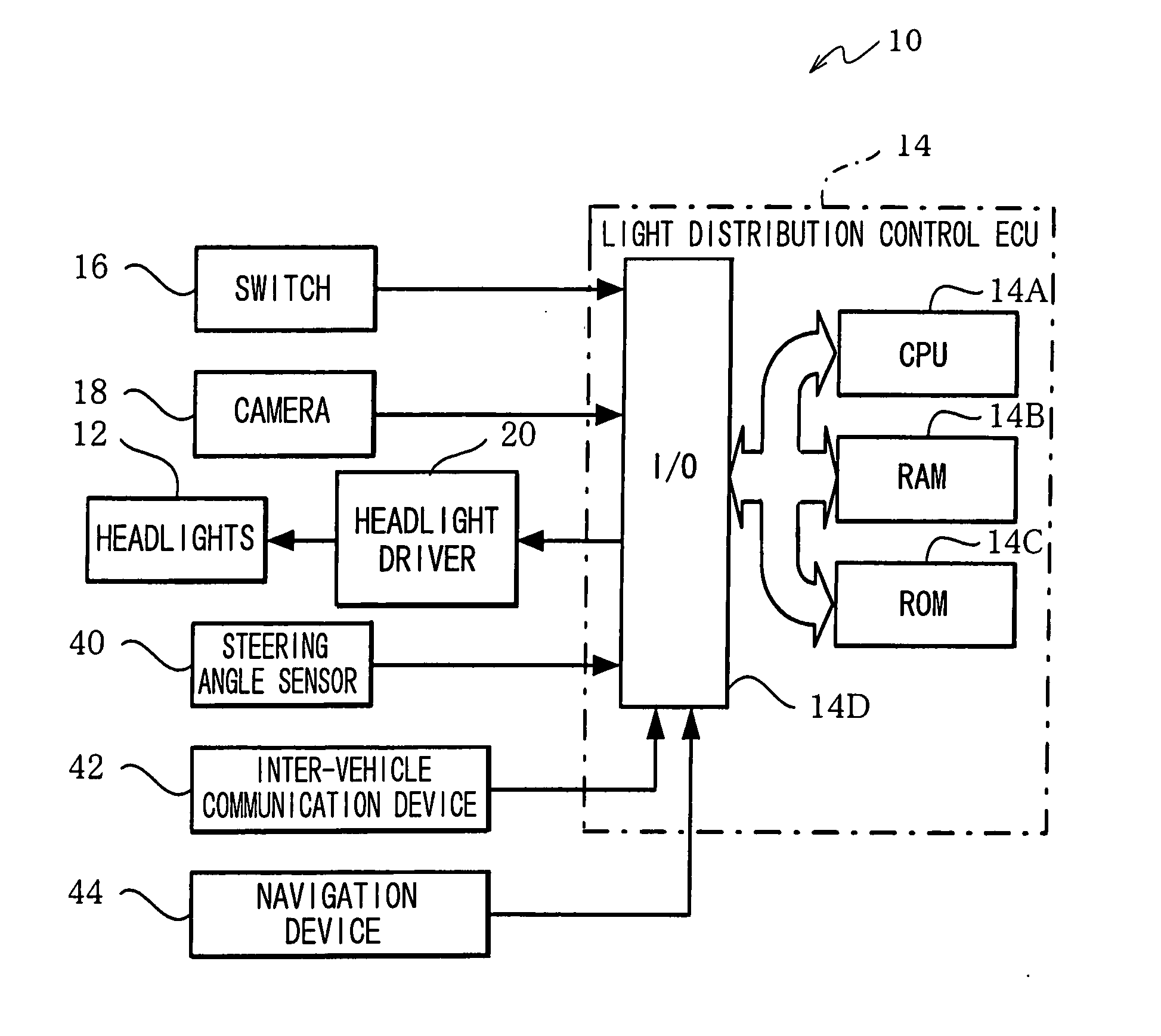
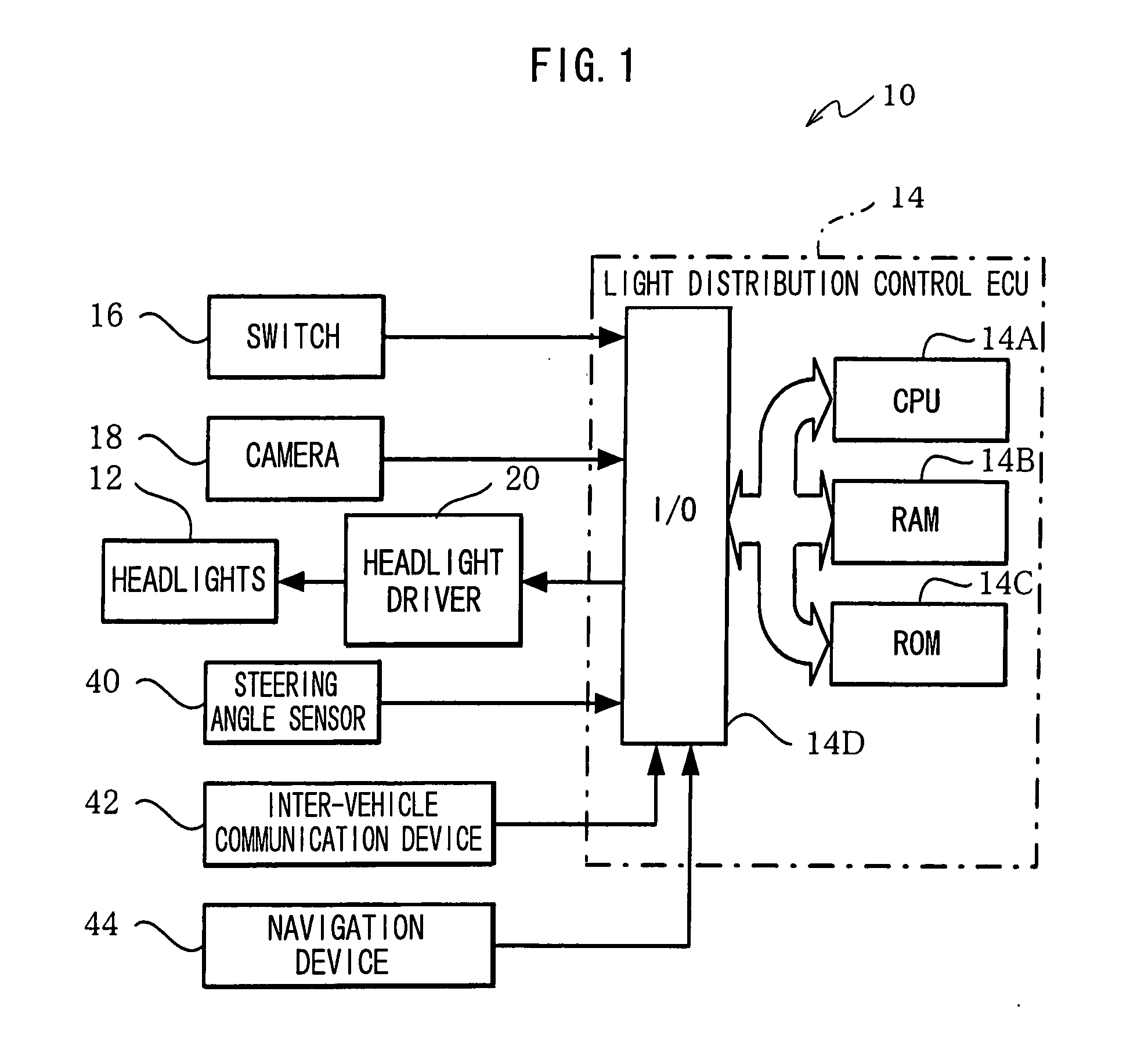
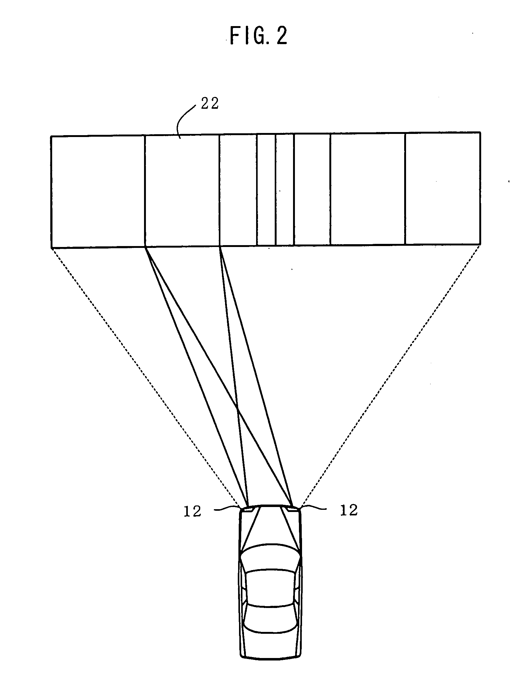
However, in the technology described in JP-A No. 2006-21631, when there are many target objects, or when the situation around the subject vehicle changes rapidly such as when approaching an intersection, the processing load of image processing and the like with respect to the image photographed by the camera rises, and there is the potential for this to cause delays in control.

Method used


Image

  • Vehicular illumination system
  • Vehicular illumination system
  • Vehicular illumination system

Examples


first modification example

[0092]In the above-described embodiment, when the predictive light distribution control is performed, a change in the vehicle angle is predicted in consideration of an oncoming vehicle entering an intersection from a direction intersecting the traveling direction of the subject vehicle is traveling. As shown in FIG. 10, when the traffic signal at the intersection is red, and when the subject vehicle is traveling, the oncoming vehicle in the direction intersecting the traveling direction of the subject vehicle is stopped at the red traffic signal, so that when a change in the vehicle angle is predicted, parameters relating to the movement of the oncoming vehicle can be decreased in comparison to when the oncoming vehicle is traveling.

[0093]In a first modification example, the predictive light distribution control is performed in consideration of a case where an oncoming vehicle side traffic signal at an intersection is red and the oncoming vehicle is stopped at the traffic signal. Th...

second modification example

[0099]In the preceding embodiment, when the predictive light distribution control is performed, the vehicle angle is predicted assuming a case where the angle formed between the traveling direction of the subject vehicle and the traveling direction of an oncoming vehicle is arbitrary, but in the case of an orthogonal intersection, that is, when the traveling direction of the subject vehicle and the traveling direction of an oncoming vehicle are orthogonal to each other, there is no need that the parameters relating to the movement of the oncoming vehicle be divided into the X and Y-axis directions when predicting the change in the vehicle angle, and consequently the calculation parameters can be reduced in comparison to the preceding embodiment.

[0100]In a second modification example, the predictive light distribution control is performed in consideration of when the traveling direction of the subject vehicle and the traveling direction of an oncoming vehicle are orthogonal to each o...


PUM


Abstract

A vehicular illumination system includes a vehicular illumination unit whose light distribution is changeable, a detection unit that detects an illumination target, and an acquisition unit that acquires load information representing a processing load when processing is performed to controls the light distribution of the vehicular illumination unit based on the relative displacement between the subject vehicle and the illumination target detected by the detection unit. Further, the vehicular illumination system includes a control unit that is capable of plural types of light distribution control, in each of which the processing load is different, and that controls the light distribution of the vehicular illumination unit by the light distribution control of a load corresponding to the processing load that is represented by the load information acquired by the acquisition unit.

Description

CROSS-REFERENCE TO RELATED APPLICATION[0001]This application claims priority under 35 USC 119 from Japanese Patent Application No. 2006-326178, the disclosure of which is incorporated by reference herein.BACKGROUND[0002]1. Technical Field[0003]The present invention relates to a vehicular illumination system, and in particular to a vehicular illumination system that controls the distribution of light emitted from headlights or the like.[0004]2. Related Art[0005]As a vehicular illumination system that controls the light distribution of headlights or the like, the technology described in Japanese Patent Application Laid-Open (JP-A) No. 2006-21631, for example, has been proposed.[0006]In the technology described in JP-A No. 2006-21631, it is proposed to provide: plural light sources that illuminate respectively different regions to form a predetermined overall light distribution pattern including a main light distribution portion and a peripheral light distribution portion; a camera tha...

Claims


Application Information

Patent Timeline
IPC IPC(8): B60Q1/08F21W107/10
CPCB60Q1/085B60Q1/143B60Q2300/45B60Q2300/122B60Q2300/42B60Q2300/056
Inventor WATANABE, SHINYA
Owner TOYOTA JIDOSHA KK
Features
  • Generate Ideas
  • Intellectual Property
  • Life Sciences
  • Materials
  • Tech Scout
  • Unparalleled Data Quality
  • Higher Quality Content
  • 60% Fewer Hallucinations
Learn More