Microchannel chip and converging device
a microchannel chip and converging device technology, applied in the field of microchannel chips, can solve the problems of difficult to stably mix two liquids each having a fixed quantity with each other, liquid transported under pressure may leak out from the atmospheric release part to the outside, and achieve the effect of stably mixing
- Summary
- Abstract
- Description
- Claims
- Application Information
AI Technical Summary
Benefits of technology
Problems solved by technology
Method used
Image
Examples
first embodiment
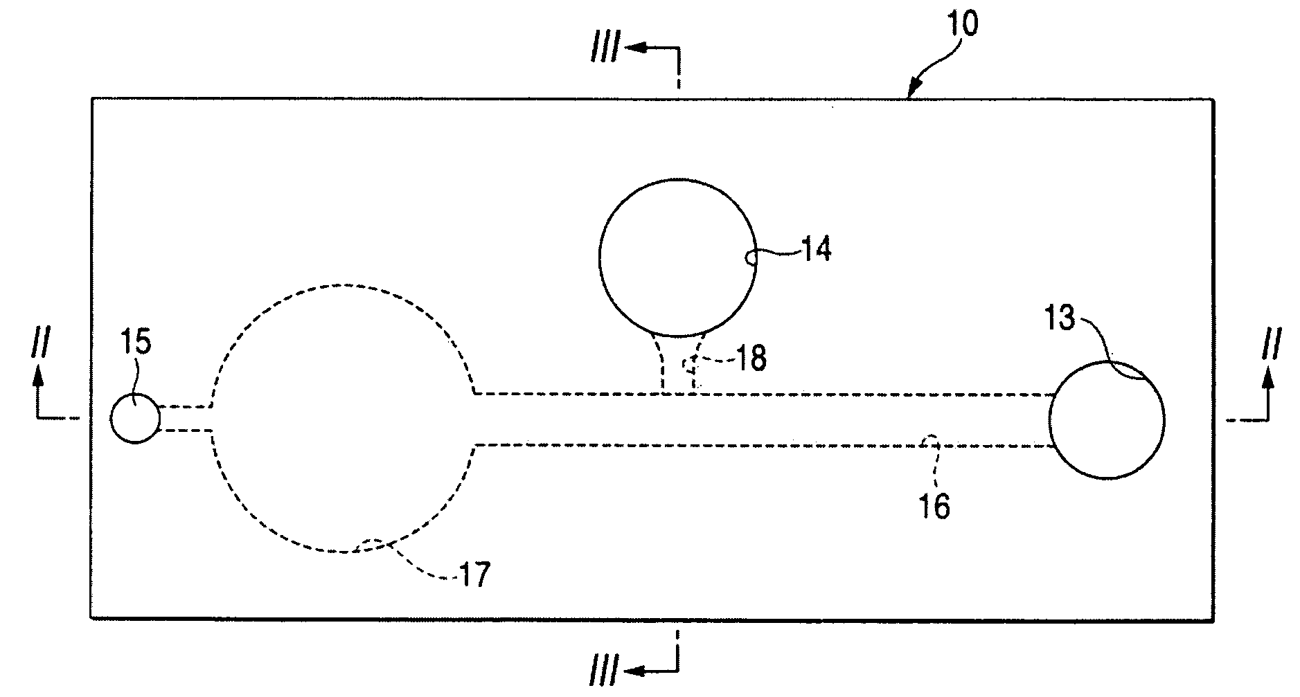
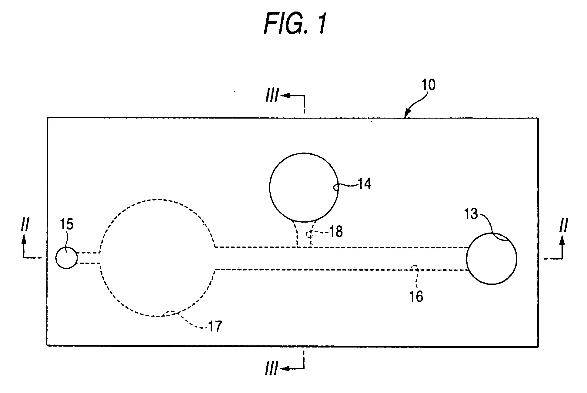
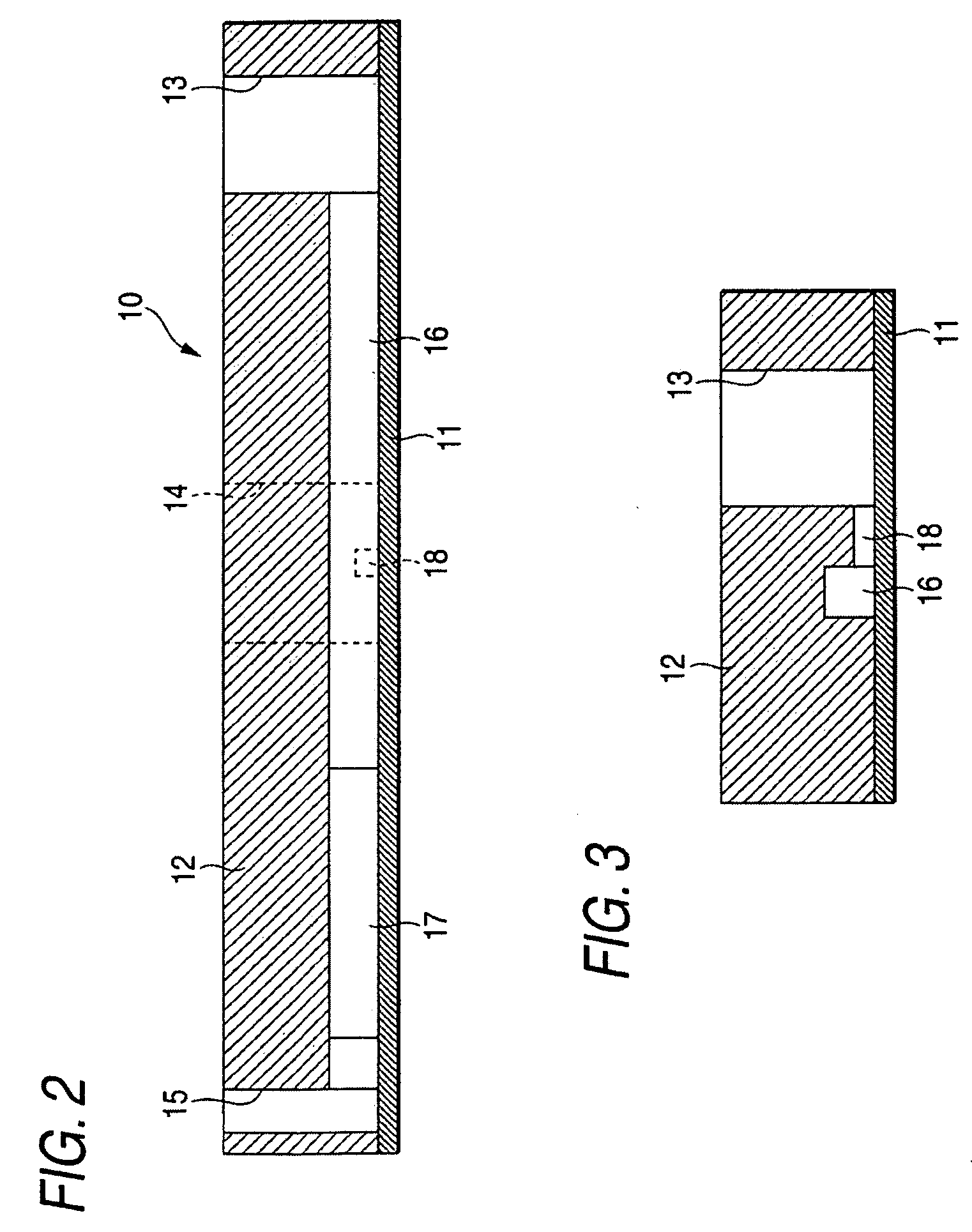
[0051]FIG. 1 is a top view of a microchannel chip for mixing two liquids according to an embodiment of the invention, FIG. 2 is a sectional view taken on line II-II in FIG. 1, and FIG. 3 is a sectional view taken on line III-III in FIG. 1.
[0052]A microchannel chip for mixing two liquids 10 according to the embodiment has a resin material 12 of a polymer, etc., deposited on a rectangular substrate 11 by injection molding, etc. At this time, the following port sections and channels are formed.
[0053]The microchannel chip for mixing two liquids 10 in the example shown in the figure is provided with three port sections 13, 14, and 15. The first port section 13 is provided in the right end portion of the chip 10, the second port section 14 is provided at the center to the top side of the chip 10, and the third port section 15 is provided in the left end portion of the chip 10. Each of the port sections 13, 14, and 15 is a columnar hole having an opening in the top face of the chip 10 and ...
second embodiment
[0069]FIG. 6 is a configuration drawing to show an embodiment of a converging device for mixing two liquids of the invention. The converging device for mixing two liquids of the embodiment includes the microchannel chip for mixing two liquids 10 previously described with reference to FIGS. 1 to 5C, a liquid arrival detection sensor 19, and a liquid delivery device 20.
[0070]The liquid arrival detection sensor 19 is provided in the proximity of the opening end of the second channel 18 on the side of the first channel 16 and is a sensor for detecting that the liquid sample A proceeding in the first channel 16 arrives at the opening end of the second channel 18; for example, it is implemented as a reflection fiber sensor.
[0071]The liquid delivery device 20 includes a connector 21 connected to the opening of the third port section 15, a connector 22 connected to the opening of the second port section 14, a decompression unit 23 connected to the third port section 15 through the connector...
third embodiment
[0080]FIG. 8 is a drawing of the configuration of a converging device for mixing two liquids according to another embodiment of the invention. The converging device for mixing two liquids of the embodiment includes the microchannel chip for mixing two liquids 10 previously described with reference to FIG. 1, the liquid arrival detection sensor 19 previously described with reference to FIG. 6, and a liquid delivery device 30.
[0081]The liquid delivery device 30 includes a connector 31 connected to the opening of the first port section 13, a connector 32 connected to the opening of the third port section 15, a compression and decompression unit 33, and solenoid valves 34 (called SV1 in the description with FIG. 9), 35 (called SV2 in the description with FIG. 9), and 36 (called SV3 in the description with FIG. 9) of three ports for performing the operation described later.
[0082]FIG. 9 is a flowchart to show an operation procedure of the converging device for mixing two liquids shown in ...
PUM
 Abstract
Description
Claims
Application Information
 - R&D
- Intellectual Property
- Life Sciences
- Materials
- Tech Scout
- Unparalleled Data Quality
- Higher Quality Content
- 60% Fewer Hallucinations
Browse by: Latest US Patents, China's latest patents, Technical Efficacy Thesaurus, Application Domain, Technology Topic, Popular Technical Reports.
© 2025 PatSnap. All rights reserved.Legal|Privacy policy|Modern Slavery Act Transparency Statement|Sitemap|About US| Contact US: help@patsnap.com


