High efficiency integrated processor for oily water

A technology for oily sewage and treatment, which is applied in the direction of liquid separation, grease/oily substance/suspton removal device, separation method, etc., which can solve the problems of high operating cost, many processing equipment, and difficulty in meeting compliance.

Active Publication Date: 2011-11-23
云南今业生态建设集团有限公司
View PDF6 Cites 5 Cited by
  • Summary
  • Abstract
  • Description
  • Claims
  • Application Information

AI Technical Summary

Problems solved by technology

[0002] At present, in the national cleaning industry, for parts in industries such as metal stamping, electroplating coating, automobile manufacturing, and electronic appliance manufacturing, after processing, oil removal and rust removal are basically done by adding surfactants to water pumps as cleaning fluids. The active agent in the liquid forms an emulsified oil during the degreasing process, because this emulsified oil has strong hydrophilicity; when the traditional oily sewage treatment method is used, the oil-water separation effect is not ideal, and the separated water is still in an emulsified state , turbidity, SS, COD, BOD and other indicators are less reduced, and it is difficult to meet the discharge indicators meeting the national environmental protection requirements. The separated sewage needs to be treated once again, that is, secondary treatment is added, resulting in more treatment equipment. There are many processing links and high operating costs. Some integrated processors for oily sewage have been announced in Chinese patents, such as "Oily Wastewater Processor" with patent number 01233432.4. It is not suitable for the treatment of domestic oily sewage generated in the environment, and it is not suitable for sewage oily water processors in related industries

Method used


Image

  • High efficiency integrated processor for oily water
  • High efficiency integrated processor for oily water

Examples


Embodiment Construction

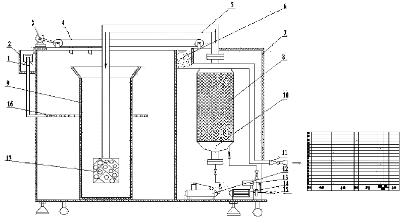
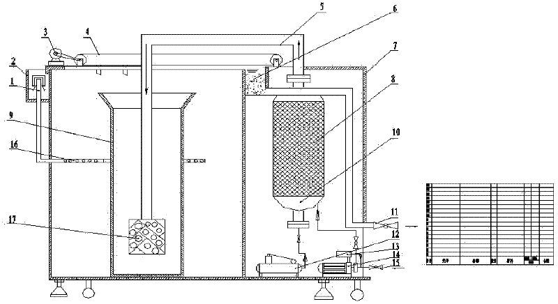
[0011] The high-efficiency oily and sewage integrated processor of the present invention will be further described below in conjunction with the accompanying drawings.

[0012] In the high-efficiency oil-sewage integrated processor shown in the accompanying drawings, the box body 7 is divided into two cavities by a partition, and a water pump 14 and an air compressor 12 are respectively arranged at the lower part of one side of the cavities; There is a water inlet valve 15, the water pipe behind the water inlet valve 15 is connected with a medicine box 13, the water outlet pipe is connected with the bottom of the dissolved air tank 10 in the same cavity, and the air outlet pipe of the air compressor 12 is also connected with the bottom of the dissolved air tank 10. At the bottom, filler 8 is arranged in the dissolved air tank 10, and the dissolved air water pipe 5 is connected to the top of the dissolved air tank 8, and the dissolved air water pipe 5 runs through the guide tube...


PUM


Abstract

The invention discloses a high efficiency integrated processor for oily water. The housing of the integrated processor is divided into two cavities by a division plate, a water pump and an air compressor is arranged at the lower part of the cavity at one side, and an induction valve and a medicament barrel are sequentially connected on the inlet pipe of the water pump; the outlet pipe of the water pump is connected with the bottom of a dissolved air vessel which is provided with filling materials, the outlet duct of the air compressor is also connected with the bottom of the dissolved air vessel, an dissolved air water pipe connected with the top of the dissolved air vessel passes through a guide shell arranged in the cavity at the other side and reaches the bottom of the guide shell, the top end of the dissolved air water pipe is provided with a releaser, the cavity with the guide shell is also provided with a coil set, the outlet of which is arranged in a rain spout outside on the housing; a slag scrapping means and an operation track cooperated with the slag scrapping means are provided right above the housing, and a slag collecting groove is arranged right below the end of the operation track. According to the invention, most parts are integrated into the single housing, thereby realizing integrated processing; chemical flocculation, physical filtration and air floatation and the like are used for integrated treatment of sewage, and therefore oily water is treated to satisfy the effluent standard only once and for all.

Description

technical field [0001] The invention relates to a sewage treatment device, in particular to an integrated oil and sewage processor which is suitable for metal stamping, electroplating coating, automobile manufacturing, electronic appliance manufacturing and other industries and for treating oily sewage generated in degreasing and cleaning processes. Background technique [0002] At present, in the national cleaning industry, for parts in industries such as metal stamping, electroplating coating, automobile manufacturing, and electronic appliance manufacturing, after processing, oil removal and rust removal are basically done by adding surfactants to water pumps as cleaning fluids. The active agent in the liquid forms an emulsified oil during the degreasing process, because this emulsified oil has strong hydrophilicity; when the traditional oily sewage treatment method is used, the oil-water separation effect is not ideal, and the separated water is still in an emulsified stat...

Claims


Application Information

Patent Timeline
Patent Type & Authority Applications(China)
IPC IPC(8): C02F1/40
Inventor 卿小燕邓辅唐曾郴林
Owner 云南今业生态建设集团有限公司
Why Eureka
Try Eureka