Totally aerated combustion burner

a technology of combustion burner and aerated combustion chamber, which is applied in the direction of burners, combustion types, combustion processes, etc., can solve the problems of increasing cost, affecting the efficiency of combustion, and reducing so as to reduce the number of burner parts, the effect of reducing the pressure loss of the primary air and widening the breadth

Inactive Publication Date: 2013-04-18
RINNAI CORP
View PDF20 Cites 6 Cited by
  • Summary
  • Abstract
  • Description
  • Claims
  • Application Information

AI Technical Summary

Benefits of technology

[0013]According to this arrangement, the primary air is obstructed by the baffle plates and does not collide with the fuel gas to be ejected from each of the nozzle holes. It is consequently possible to make the fuel gas surely collide with the wall plate without being influenced by the primary air even at the time of a weak burn at which the ejection of the fuel gas is made small in quantity. The mixing of the fuel gas and the primary air can thus be accelerated. Moreover, because the rising plate portions on respective lateral sides of each baffle plate are inclined so that the upper-side distance of the rising plate portions becomes larger, the primary air does not hit the fuel gas ejected from each of the nozzle holes even if the nozzle holes are somewhat deviated sidewise relative to the baffle plates. Accurate alignment of the nozzle holes and the baffle plates therefore becomes unnecessary.
[0014]By the way, it is also conceivab...

Problems solved by technology

However, in the prior art as described above, if the position of the opening-free portion in the inclined plate and the position of the nozzle holes are out of lateral alignment with each other, the fuel gas ejected from the nozzle holes sometimes does not collide with the opening-free portion of the inclined plate but enters the openings, resulting in poor mixing of the fuel gas and the primary air.
As a result, the assembling of the above-mentioned parts becomes troublesome, thereby bringing about an increase in cost.
Accurate alignment betw...

Method used


Image

  • Totally aerated combustion burner
  • Totally aerated combustion burner
  • Totally aerated combustion burner

Examples


Embodiment Construction

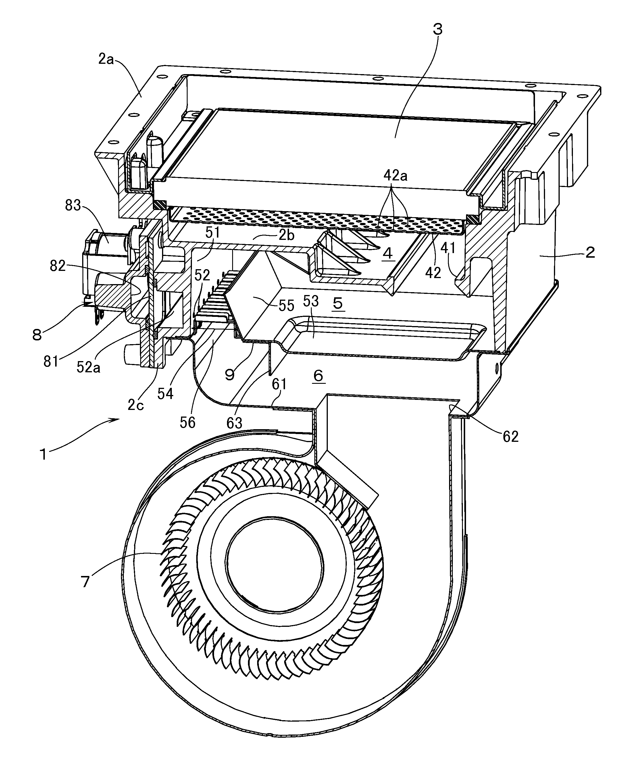
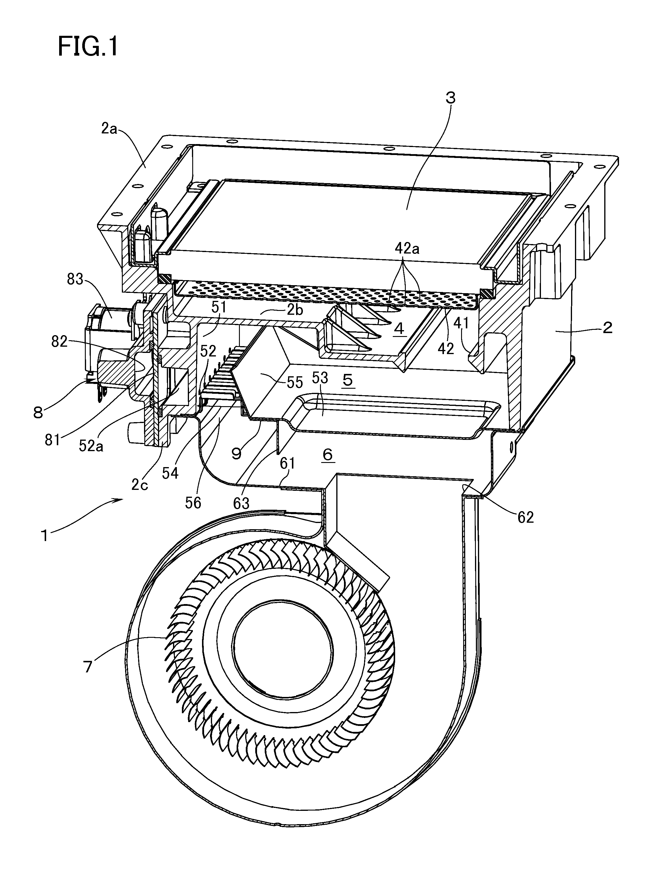
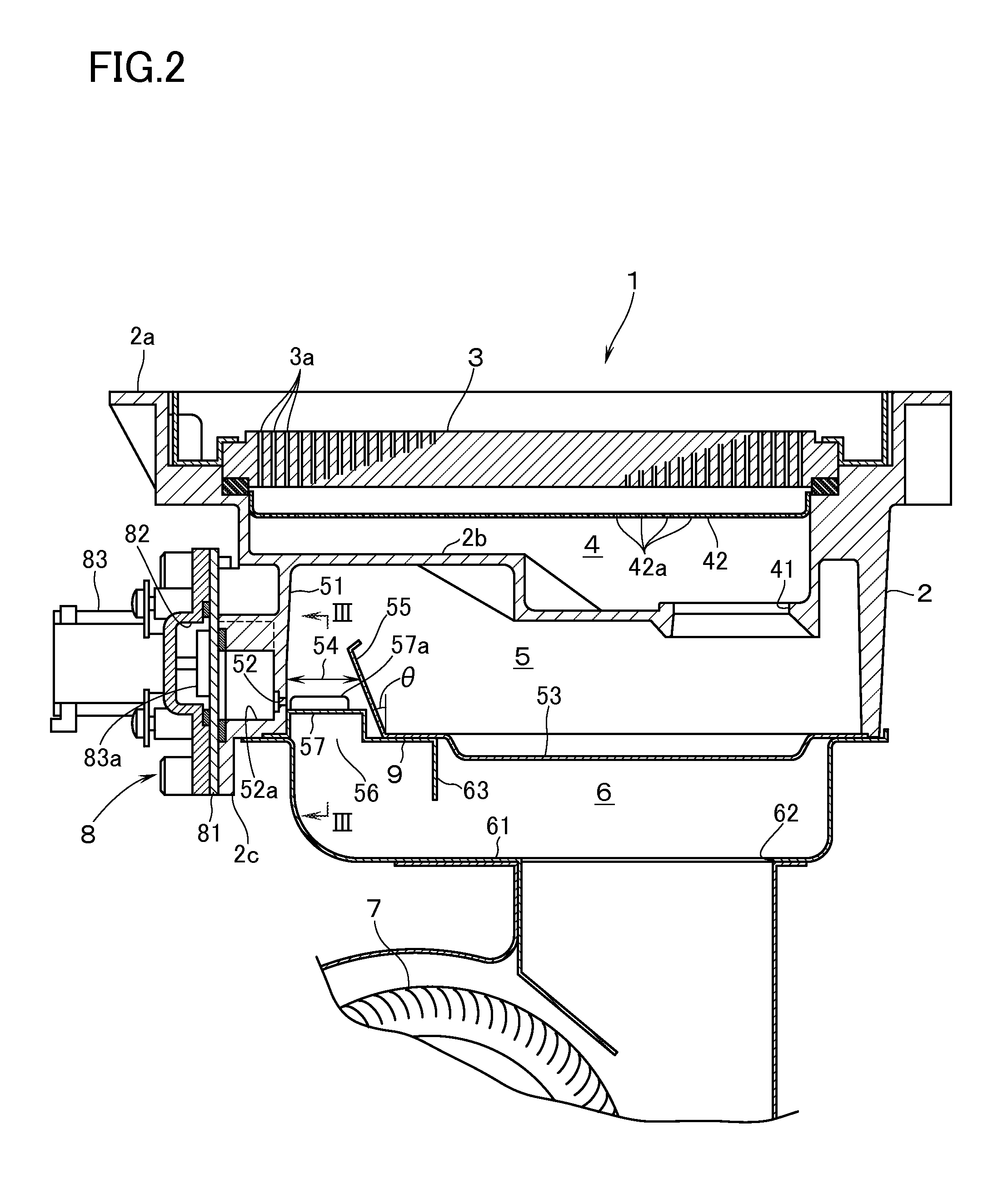
[0019]FIGS. 1 and 2 show a totally aerated combustion burner 1 according to one embodiment of the invention. The burner 1 has a burner main body 2 which is formed into a box shape, and a combustion plate 3 which is made of ceramics and which is provided with a multiplicity of flame holes 3a. By the way, the flame holes 3a are not illustrated in FIG. 1. The description is made in the following on condition that such a side of the burner as is equipped with the combustion plate 3 is defined as an upper surface, that the width direction of the burner 1 is defined as a lateral direction, and that the depth direction of the burner 1 is defined as a longitudinal direction.

[0020]On an outer peripheral part of the upper surface of the burner main body 2, there is disposed a flange portion 2a to which is connected a lower end of a combustion housing (not illustrated) in which are housed an object to be subjected to heating, such as a heat exchanger, and the like. Further, the burner main bod...


PUM


Abstract

A totally aerated combustion burner having a combustion plate with a multiplicity of flame holes includes a distribution chamber, a mixing chamber, and an air supply chamber. The mixing chamber has a front surface with a plurality of nozzle holes disposed in parallel with, and at a lateral distance from, one another so that a fuel gas to be ejected from the nozzle holes and the primary air from the air supply chamber get mixed in the mixing chamber. A wall plate is disposed upright on a bottom surface of the mixing chamber in a manner to lie opposite to the front surface of the mixing chamber while leaving a ventilation clearance to the front surface. An air inlet is formed in such a portion at the bottom surface of the mixing chamber as to face the ventilation clearance.

Description

BACKGROUND OF THE INVENTION[0001]1. Field of the Invention[0002]The present invention relates to a totally aerated combustion burner (or a fully primary aerated burner) which is equipped with a combustion plate having formed therein a multiplicity of flame holes and which discharges a premixed gas from the flame holes to perform totally aerated combustion (or fully primary aerated combustion) of the gas.[0003]2. Description of the Related Art[0004]As this kind of totally aerated combustion burner, there is known one described in JP-2001-090913 A. Suppose that such a side of the burner as is equipped with a combustion plate is defined as an upper surface, that a width direction of the burner is defined as a lateral direction, and that a depth direction of the burner is defined as a longitudinal direction, respectively. Then the burner has: a distribution chamber facing the lower surface of the combustion plate; a mixing chamber located on the lower side of the distribution chamber; a...

Claims


Application Information

Patent Timeline
IPC IPC(8): F23D14/62
CPCF23D14/62F23D14/34F23D14/02
Inventor AKAGI, KAZUYUKI
Owner RINNAI CORP
Why Eureka
Try Eureka