Delay Regulating Device

Inactive Publication Date: 2008-06-05
FUJITSU LTD
View PDF6 Cites 6 Cited by
  • Summary
  • Abstract
  • Description
  • Claims
  • Application Information

AI Technical Summary

Benefits of technology

[0043]The present invention aims at providing a delay regulating device capable of setting the timing of a reference si

Problems solved by technology

Although there are various methods of setting a tap coefficient, an amount of delay depends on the setting of each tap coefficient.
However, the conventional system of adjusting an amount of delay has the following problem.
In this case, the phase adjustment is performed with a shifted delay, a correct phase cannot

Method used


Image

  • Delay Regulating Device
  • Delay Regulating Device
  • Delay Regulating Device

Examples


Embodiment Construction

[0057]According to this mode for embodying the present invention, the delay regulation is performed in the following procedure to solve the above-mentioned problem.

(1) delay regulation in a clock unit by correlation calculation

(2) filter tap delay regulation in 1 / 128 clock unit by correlation calculation

(3) filter tap delay regulation in 1 / 128 clock unit by error calculation

[0058]The delay regulation in (1) above is not limited to one clock unit. The delay regulation in (2) and (3) is also not limited to the 1 / 128 clock unit, but can be any unit smaller than the delay regulation unit of (1) above.

[0059]By performing the above-mentioned procedure, the correlation calculation of (2) above requires no phase adjustment, thereby performing the filter tap delay regulation without a large shift.

[0060]FIG. 9 shows the state of the amount of delay and correlation value in the 1 / 128 clock unit.

[0061]The horizontal axis shows the amount of delay in the 1 / 128 clock unit, and the vertical axis s...


PUM


Abstract

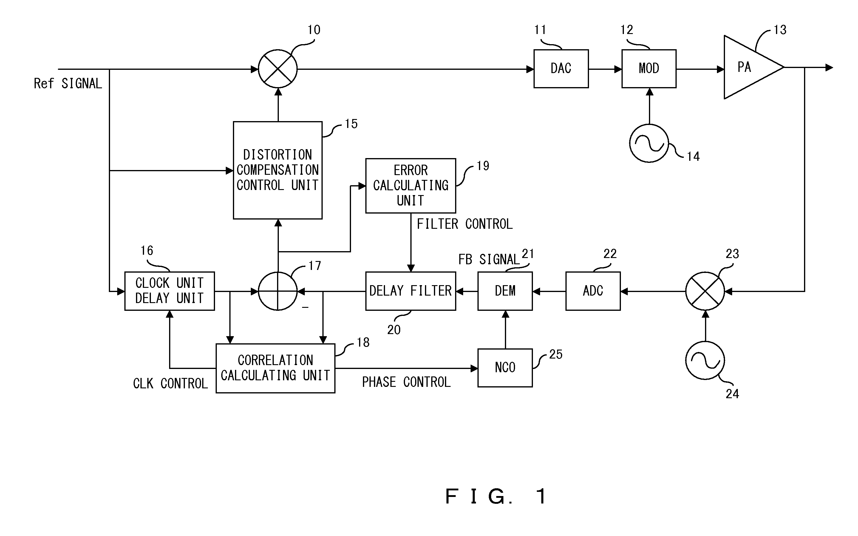
In a delay regulating device, delay regulation is performed using a delay circuit performing delay regulation in a clock unit and a delay filter performing delay regulation in a tap unit smaller than the clock unit. The delay regulation is performed so as to obtain the maximum value of the correlation value and the minimum value of the error signal. First the delay circuit based on the clock unit is used to control the delay amount of the reference signal so as to obtain the maximum value of the correlation value. The delay filter is used to control the delay amount of the feedback signal so as to obtain the maximum value of the correlation value. Phase adjustment of the reference signal and the feedback signal is performed. The delay amount of the feedback signal is regulated so as to minimize the error signal unit using the delay filter.

Description

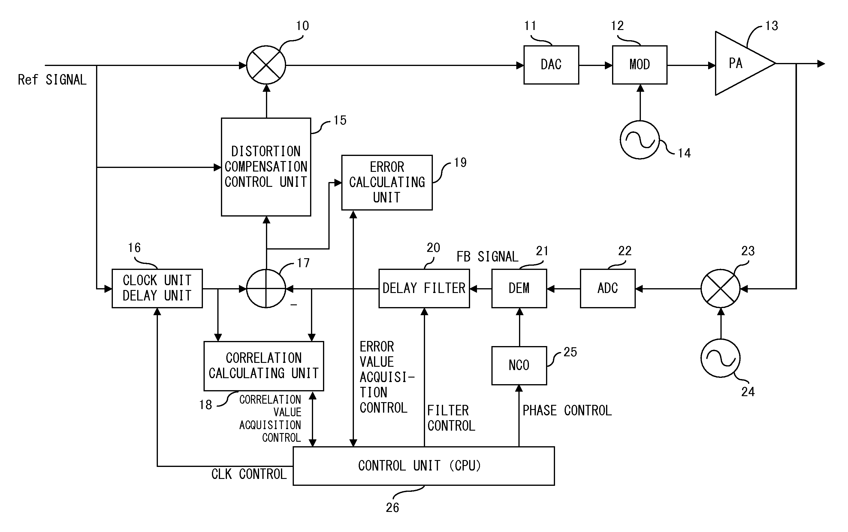
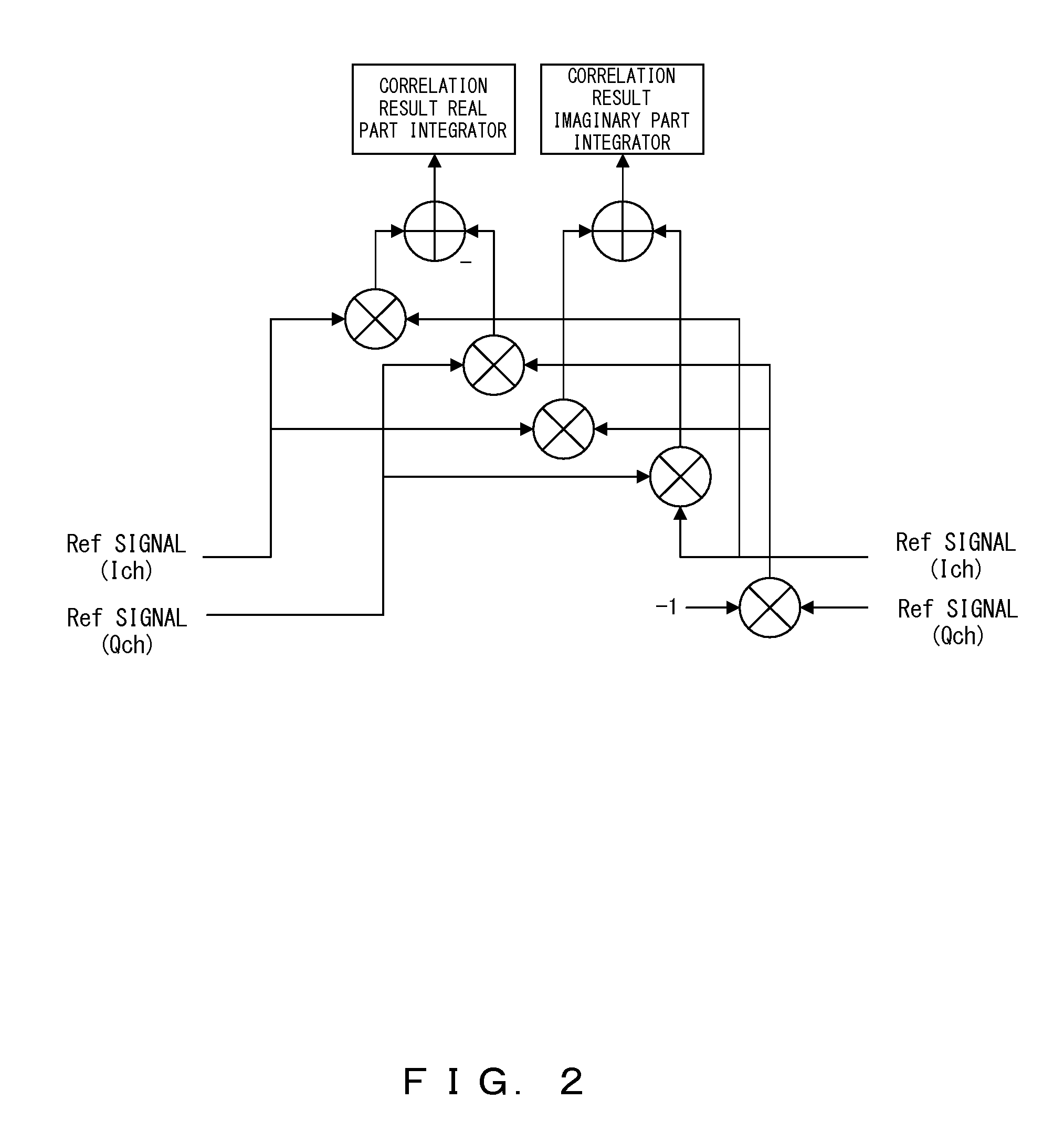
CROSS-REFERENCE TO THE RELATED APPLICATION[0001]This application is a continuation application of the international patent application No. PCT / JP2005 / 13974, filed on Jul. 29, 2005.BACKGROUND OF THE INVENTION[0002]1. Field of the Invention[0003]The present invention relates to a delay regulating device for a reference signal and a feedback signal in an adaptive predistorter (APD) type distortion compensation device.[0004]2. Description of the Related Art[0005]When distortion compensation is performed in the APD system, delay regulation is required to control timing between a reference signal (Ref signal) and a feedback signal (FB signal).[0006]FIG. 1 is a block diagram of a transmission board to which the distortion compensation in the APD system is applied.[0007]The reference signal (Ref signal) is a baseband signal of a transmission signal. The reference signal is input to a multiplier 10, multiplied by a distortion compensation coefficient from a distortion compensation control un...

Claims


Application Information

Patent Timeline
IPC IPC(8): H04L27/06
CPCH03F1/3247H03F2201/3233H03F1/3294H03F1/32
Inventor OHBA, TAKESHIFUNYU, YASUHITOSHAKO, HIDEHARU
Owner FUJITSU LTD
Why Eureka
Try Eureka