[0005]Accordingly, a primary object of the present invention is to solve the above-mentioned prior art problems and to provide an improved bearing roller chain, in which the seal performance of a seal mechanism is sufficient, achieving prevention of invasion or entry of foreign substances from the outside, prevention of lubricating oil leakage to the outside and the like. An improvement of
wear resistant life of the bearing roller and the suppression of rotation failure of the roller can also be achieved and an increase in the traveling resistance of the chain can be avoided.
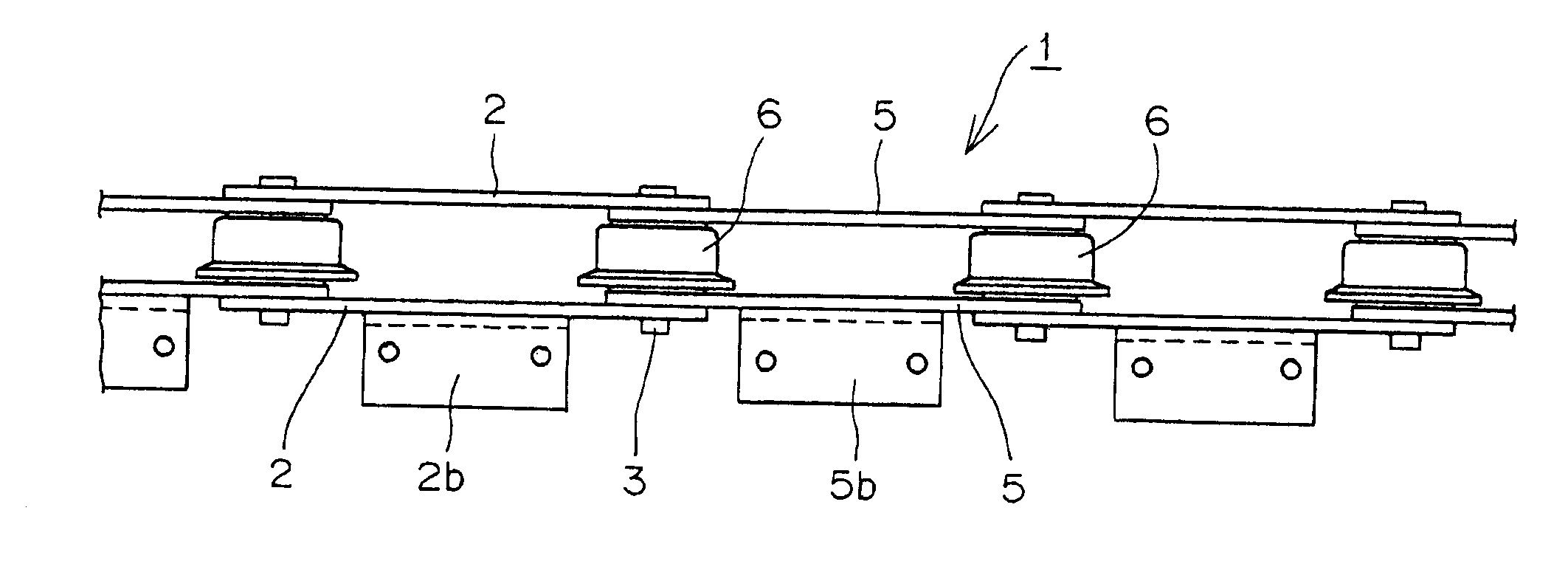
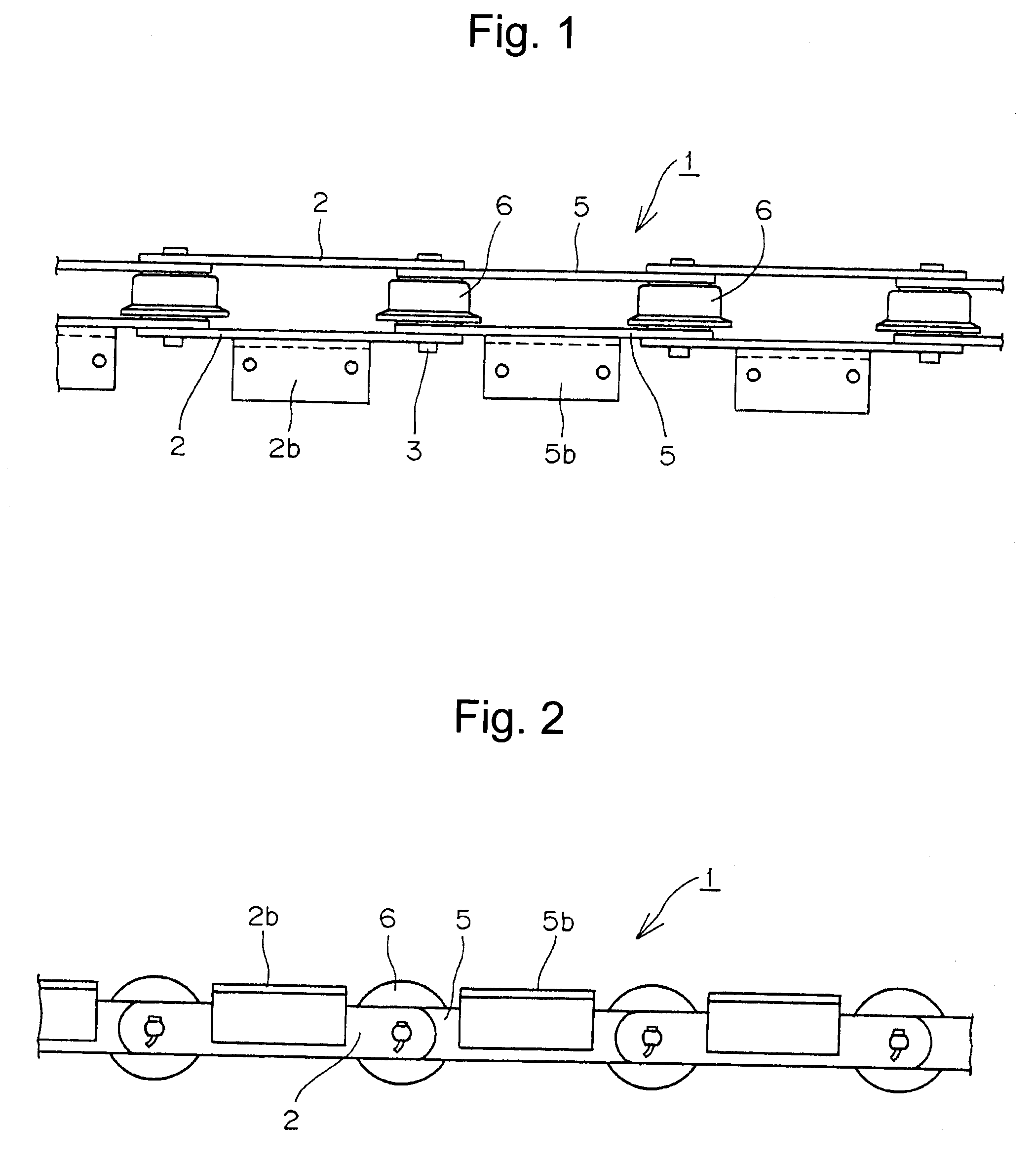
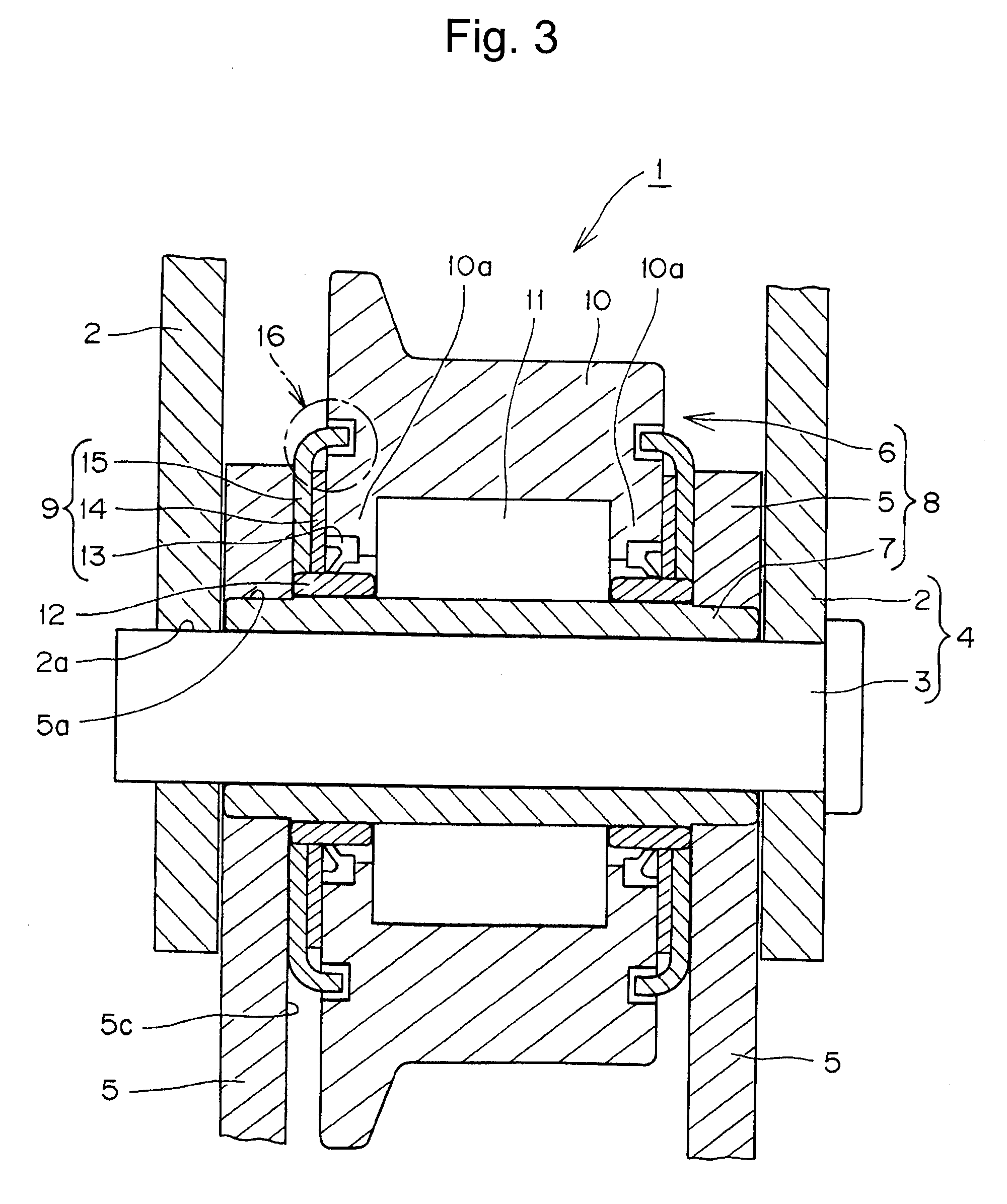
[0007]The present invention provides a bearing roller mounted for rotation on a bush and comprising a first hollow roller having inward flanges on both inner circumferential sides, a plurality of second anti-friction rollers disposed between the first roller and the bush in parallel with the center axial line of the bush, and side rings mounted on the bush and coming into
close contact with a side surface of the anti-friction rollers and an inner surface of the inner link plates on both sides of the bearing roller. Any axial (direction of thrust) shift of the bearing roller positioned and mounted between the pair of inner link plates is prevented.
[0008]The seal mechanism comprises an annular oil seal member, a spacer, and a disk-shaped seal member having an outer
flange extended toward an outer side surface of said roller. These components are sequentially disposed from the outer side surfaces of the anti-friction rollers toward the inner surfaces of the inner link plates. The seal mechanism provides a multi-seal mechanism composed of the annular oil seal member, the spacer, and the disk-shaped seal member, ensuring sufficient seal performance. As a result, even in various use environments such as in a dust
atmosphere, in an atmosphere of water splashing and the like, any entry or invasion of foreign substances into the inside of the hollow bearing roller can be prevented, and at the same time preventing any leakage of lubricating oil from the inside of the hollow roller to the outside. Further, since the prevention of invasion of foreign substances is possible, the
wear resistant life of the bearing roller can be improved, suppression of rotation failure of the roller can be achieved and an increase in the traveling resistance of the chain can be avoided.
[0009]The disk-shaped seal member has a flange extended toward an outer side surface of the first roller on an outer circumferential portion and this flange loosely enters an annular concave groove concentrically formed on the outer side surface of the first roller while forming space to form a
labyrinth structure composed of the annular concave groove and the flange. This
labyrinth structure suppresses the invasion of foreign substances to the annular oil seal member side, improving the endurance of the annular oil seal member and the spacer and preventing
frictional resistance from being generated between the first roller and the disk-shaped seal member.
[0010]The annular oil seal member has an annular base portion and a pair of lip portions extended from the base portion in a forked manner. One lip portion comes into
close contact with said side ring and the other lip portion comes into close contact with the spacer. The base portion is mounted in a cavity of the hollow roller concentrically formed on an outside end portion of an inward flange of the roller. The pair of lip portions and the spacer form an annular pocket. This annular pocket is used as a lubricating oil
retainer, and a lubricating oil such as
grease, oil or the like is sealed thereinto during an
assembly of the bearing roller chain, maintaining smooth rotation of the bearing roller for a long period of time.
[0011]When the flange of the disk-shaped seal member loosely enters the annular concave groove, a labyrinth structure is formed which protects the annular oil seal member and improves the seal performance. In a case where, particularly in a bearing roller chain, a multi-seal structure is formed of the disk-shaped seal member, the spacer and the annular oil seal member, a labyrinth structure is formed by the annular concave groove on an outer side surface of the first roller and the flange. This labyrinth structure, with the spacer provided inside, and the annular oil seal member can further improve the seal performance

