Optical switch and optical waveform monitoring apparatus

a technology of optical switch and optical waveform, which is applied in the direction of transmission monitoring, multiplex communication, instruments, etc., can solve the problems of limited time resolution and difficulty in achieving a time resolution higher than 10 picoseconds

Inactive Publication Date: 2008-06-05
NEC ELECTRONICS CORP +1
View PDF1 Cites 17 Cited by
  • Summary
  • Abstract
  • Description
  • Claims
  • Application Information

AI Technical Summary

Benefits of technology

[0028]FIG. 10 is a diagram illustrating an example of an output light spect

Problems solved by technology

However, such a common optical waveform monitoring apparatus described above has a problem that the time resolution is limited by the bandwidths of the photoelectric converter 101, the trigger circuit 102, the sampling circuit 1

Method used


Image

  • Optical switch and optical waveform monitoring apparatus
  • Optical switch and optical waveform monitoring apparatus
  • Optical switch and optical waveform monitoring apparatus

Examples


Embodiment Construction

[0029]However, a conventional optical switch as illustrated in FIG. 8 has a problem that noise components are generated due to factors such as the performance limitation of a polarizer, which results in degradation of switch characteristics.

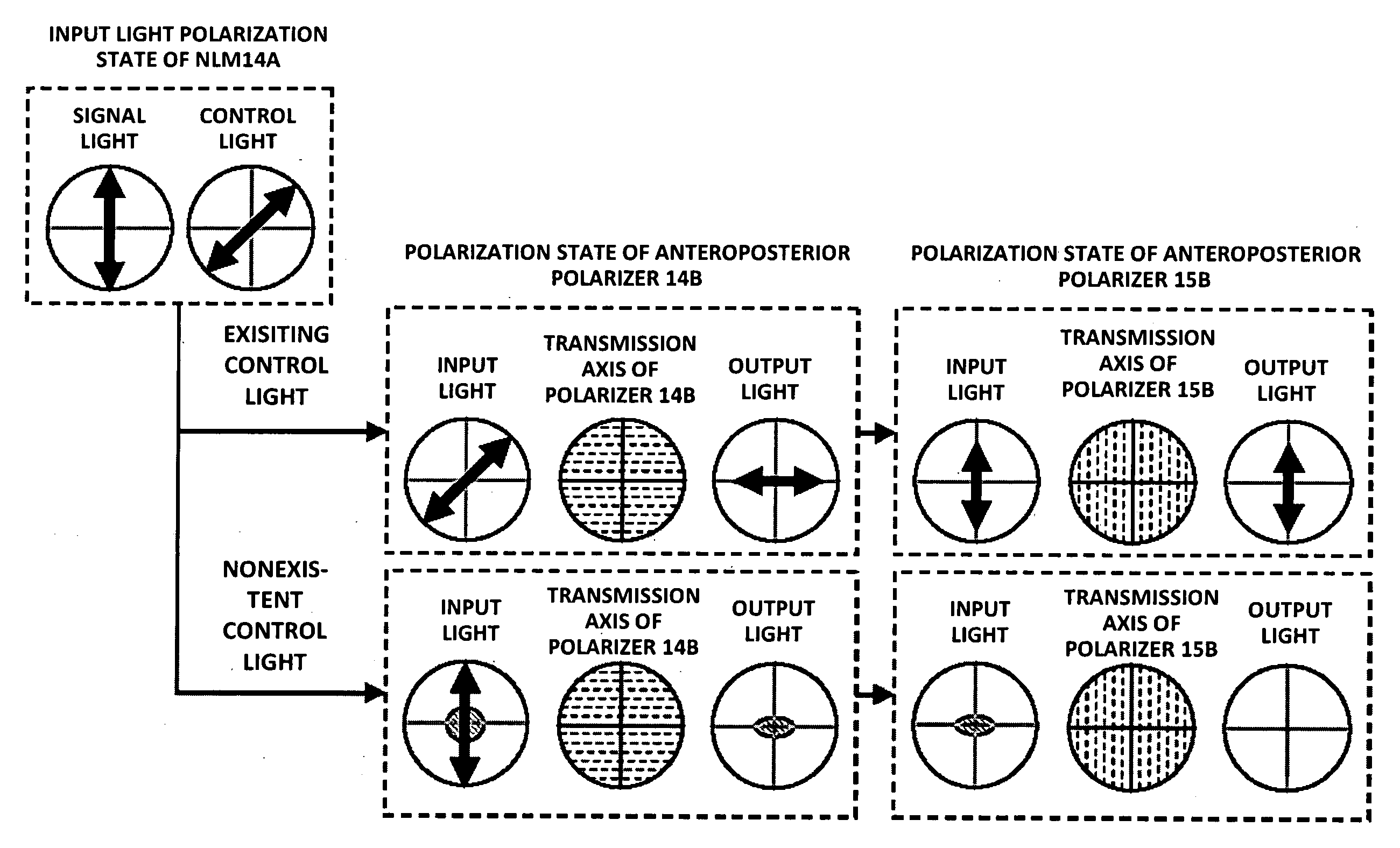
[0030]Specifically, in the above conventional optical switch, it is ideal that no light component transmits through a polarizer when no control optical pulse is present. However, in actual implementation, a significant amount of light components transmit through a polarizer due to fluctuation of signal light input to the optical switch, polarization mode dispersion (PMD) of a nonlinear medium, wavelength dependency of transmission characteristics of a polarizer, or the like. As a result, noise components are generated.

[0031]FIG. 10 shows an example of a spectrum of light transmitted through a polarizer in a case where no control light pulse is present. The power of the transmission light is minimized at a predetermined wavelength. A light compone...


PUM


Abstract

According to an aspect of an embodiment, an optical switch comprises:
    • a coupler for coupling a signal light and a control pulse;
    • a first nonlinear medium for amplifying the signal light in accordance with the polarization direction of the control pulse light by nonlinear effect;
    • a first polarizer outputting a component light in a signal light and the control pulse light in parallel with the transmission axis of the first polarizer;
    • a second nonlinear medium for changing status of polarization of the signal light by nonlinear effect; and
    • a second polarizer outputting a signal light and a control pulse light in parallel with the transmission axis of the second polarizer.

Description

BACKGROUND OF THE INVENTION[0001]The present art to optical switches extract part of signal light for output and optical waveform monitoring apparatuses monitor waveforms of light to be measured using the optical switches as optical sampling gates. In particular, the present art relates to an optical switch for extracting signal light by utilizing nonlinear effects caused by control light and an optical waveform monitoring apparatus.[0002]There is a technique, as one of basic techniques for observing optical signals, in which optical signals are converted into electric signals using optical receivers and then the electric signals are observed on electrical oscilloscopes. FIG. 6 illustrates an example of an optical waveform monitoring apparatus which has been widely used. In the optical waveform monitoring apparatus illustrated in FIG. 6, light to be measured (optical pulse) is converted into an electric signal through a photoelectric converter 101. Then, an electrical sampling pulse...

Claims


Application Information

Patent Timeline
IPC IPC(8): H04B10/00G02F1/39
CPCG01J11/00G02F1/3515G02F1/39H04J14/06H04Q2011/0045H04Q11/0005H04Q2011/0035H04Q2011/0039H04Q2011/0041H04J14/08
Inventor FUTAMI, FUMIOWATANABE, SHIGEKI
Owner NEC ELECTRONICS CORP
Why Eureka
Try Eureka