
Guided wave pipeline inspection system with enhanced focusing capability

a pipeline inspection and guided wave technology, applied in special data processing applications, measurements using magnetic resonance, data switching networks, etc., can solve the problems of difficult and dangerous pipe removal, pipeline progress is costly, and the overburden removal is not readily achievable with conventional technology, etc., and achieve the effect of economic us

Inactive Publication Date: 2008-06-05
FUKUOKA BROADCASTING CORPORATION
View PDF2 Cites 9 Cited by
  • Summary
  • Abstract
  • Description
  • Claims
  • Application Information

AI Technical Summary

Benefits of technology

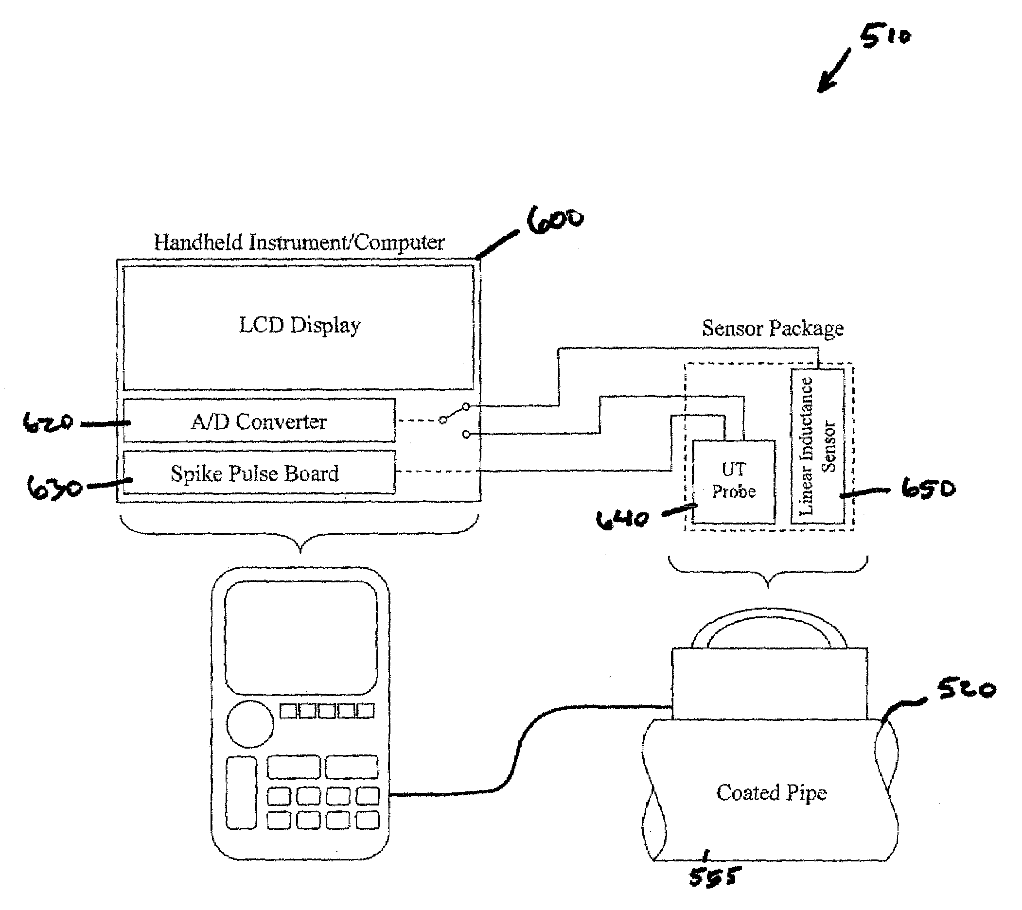
[0009]It is therefore an objective of an aspect of the present invention to provide for a pipeline inspection system that is mobile and is economical to use.
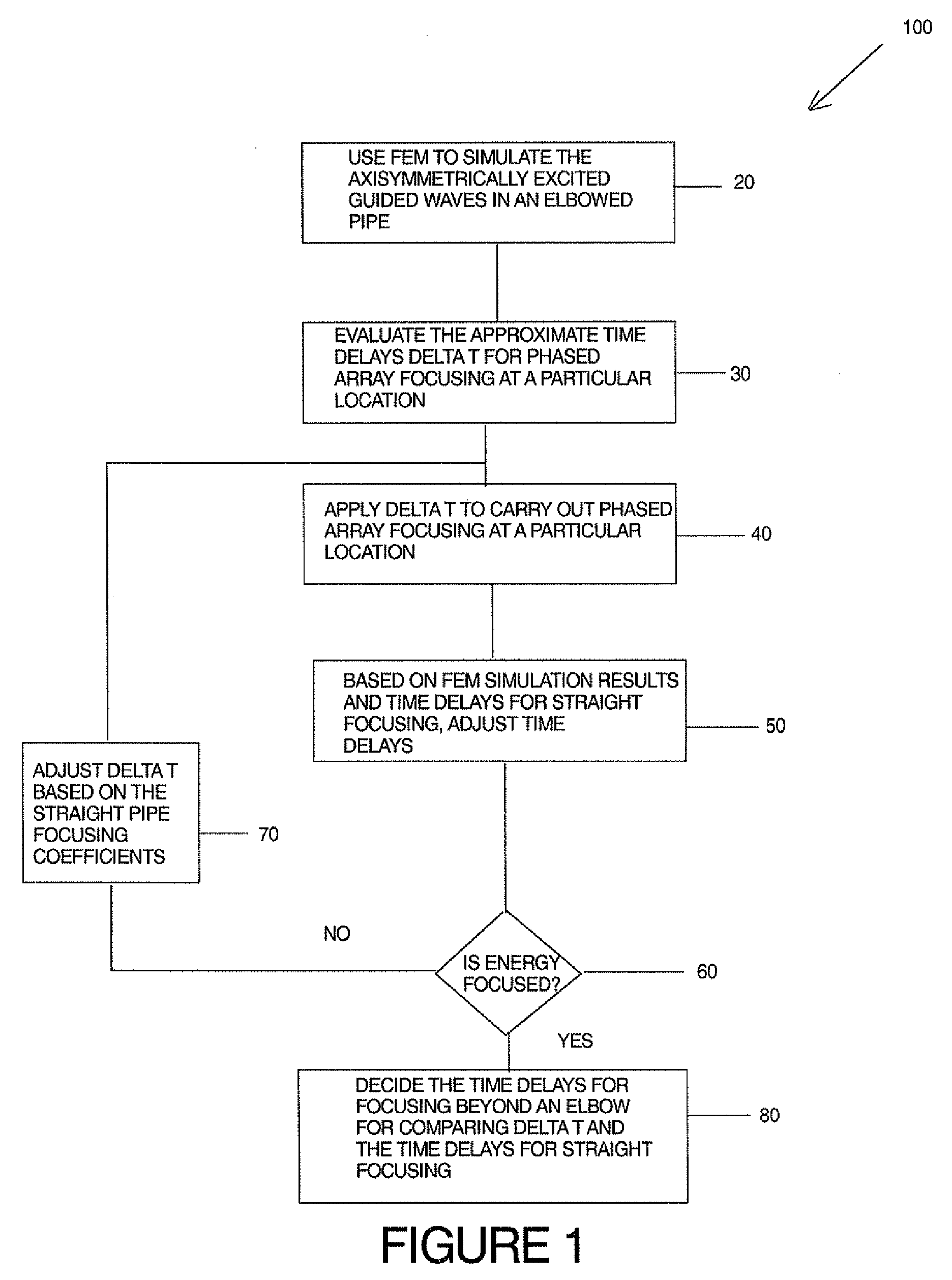
[0010]It is also an objective of an aspect of the invention to provide a pipeline inspection system that can account for changes in geometry of the pipeline so that the pipeline may be remotely inspected.
[0012]It is another objective of an aspect of the invention to provide a pipeline inspection system that will allow an investigator to pinpoint defects in a pipeline or analyze more closely a selected area of a pipeline desired by investigators.
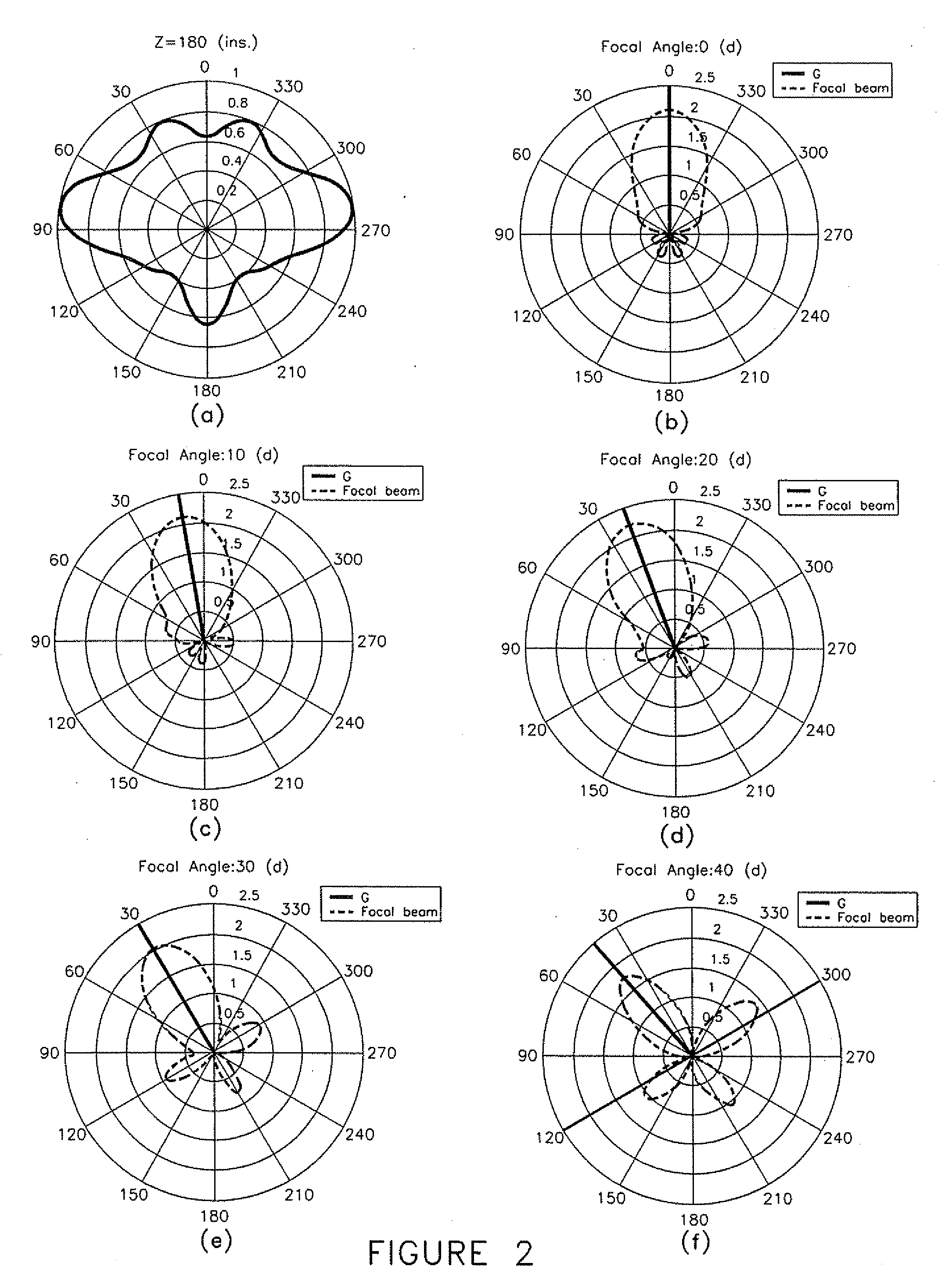
[0013]It is also an objective of an aspect of the invention to provide a system that improves upon conventional technology wherein additional focal points are created around a circumference of a member to be evaluated without the need for additional pulsing and receiving equipment.
[0020]In another exemplary embodiment, the system is configured such that the arrangement configured to send, receive and store signals uses an algorithm that minimizes data collected from the pipe.

Problems solved by technology

Analysis of pipelines in-situ is an important function that, unfortunately, is not readily achievable with conventional technology.
Removal of the overburden from a pipe is a difficult and dangerous situation for work crews that are tasked with the function.
To this end, the progress of analyzing pipelines is a costly proposition that also involves a safety concern of investigators.
Pipelines that have changes in geometry, such as elbows, moreover, cannot be readily evaluated even by remote methods.
Such access to the piping system may be impossible in certain circumstances, so these piping systems go uninspected.
These significant drawbacks of conventional systems cost excessive money to be spent by pipeline owners who desire to carefully maintain their equipment to a desired standard.

Method used


Image

  • Guided wave pipeline inspection system with enhanced focusing capability
  • Guided wave pipeline inspection system with enhanced focusing capability
  • Guided wave pipeline inspection system with enhanced focusing capability

Examples


Embodiment Construction

[0029]Referring to FIG. 3, in an exemplary embodiment of the present invention, a system 10 for inspecting pipes 20 is presented wherein a number of transducers 30 are spaced around the circumference of the pipe 20. The transducers 30 may be in separate rings 40 placed around the pipe 20 for the purpose of unidirectional propagation or increased penetration power of guided wave signals. In the illustrated exemplary embodiment, only one ring of transducers 30 is present This exemplary embodiment does not limit the system 10 in any way to one ring. The same concept applies to systems with multiple transducer rings. Referring to FIG. 6, a sample ring 40 of transducers 30 is illustrated in further detail.

[0030]In the system 10, transducers 30 are divided into segments 50, each containing a finite number of sensors 60, with a maximum number of segments 50 being equal to the number of transducers 30. Each segment 50 is individually addressable. The system 10 then contains a finite number ...


PUM

PropertyMeasurementUnit
sizeaaaaaaaaaa
sizeaaaaaaaaaa
time delayaaaaaaaaaa

Abstract

A system for inspecting a pipeline having at least two transducers divided into segments, the segments each containing a number of sensors, wherein a maximum number of segments is equal to a number of transducers, an arrangement configured to send, receive and store signals, wherein the arrangement has a number of pulser channels and a number of receiver channels, wherein the arrangement has at least one multiplexing arrangement for multiplexing signals from the arrangement; and a time delay arrangement connected to the arrangement configured to send, receive and store signals. The system may also provide for focal point skewing, near real time coating compensation for proper excitation mode, adjusted time delay capability and the ability to focus beyond changes in geometry.

Description

CROSS-REFERENCE TO RELATED APPLICATIONS[0001]This U.S. non-provisional application claims the benefit of U.S. provisional patent application 60 / 867,976 filed Nov. 30, 2006, the entirety of which application is incorporated by reference in this application.FIELD OF THE INVENTION[0002]Aspects of the invention relate to pipeline inspection. More specifically, aspects of the invention relate to providing a guided wave pipeline inspection system with enhanced focusing capability.BACKGROUND INFORMATION[0003]Analysis of pipelines in-situ is an important function that, unfortunately, is not readily achievable with conventional technology. In order to investigate pipelines, such as for defects within the materials of the pipeline, the pipelines must be readily accessible for visual / material inspection. Pipelines that extend underground, therefore, must be uncovered so that investigators may visually identify the surface of the pipe.[0004]Removal of the overburden from a pipe is a difficult a...

Claims


Application Information

Patent Timeline
Patent Type & Authority Applications(United States)
IPC IPC(8): G06F17/50G01N29/44H04L12/26
CPCG01N29/043G01N29/221G01N29/262G01N29/4472G06F2217/34G01N2291/106G01N2291/2634G06F17/5018G01N2291/0425G06F30/23G06F2113/14
Inventor OWENS, STEVEN E.ROSE, JOSEPH L.VAN VELSOR, JASON K.ZHANG, LIAVIOLI, MICHAEL J.
Owner FUKUOKA BROADCASTING CORPORATION
Learn More