Debug card

a debug card and card body technology, applied in the field of debug cards, can solve the problems of operator performing testing to be unclear regarding the debug information, the stability and reliability of new design computer systems for mass production, and the inability to convey as much information as possibl

Inactive Publication Date: 2008-06-05
HON HAI PRECISION IND CO LTD
View PDF17 Cites 10 Cited by
  • Summary
  • Abstract
  • Description
  • Claims
  • Application Information

AI Technical Summary

Problems solved by technology

During a design phase, newly designed computer systems are not stable and reliable for mass-production, and include many firmware and software bugs.
However, the seven-s

Method used


Image

  • Debug card
  • Debug card
  • Debug card

Examples


Embodiment Construction

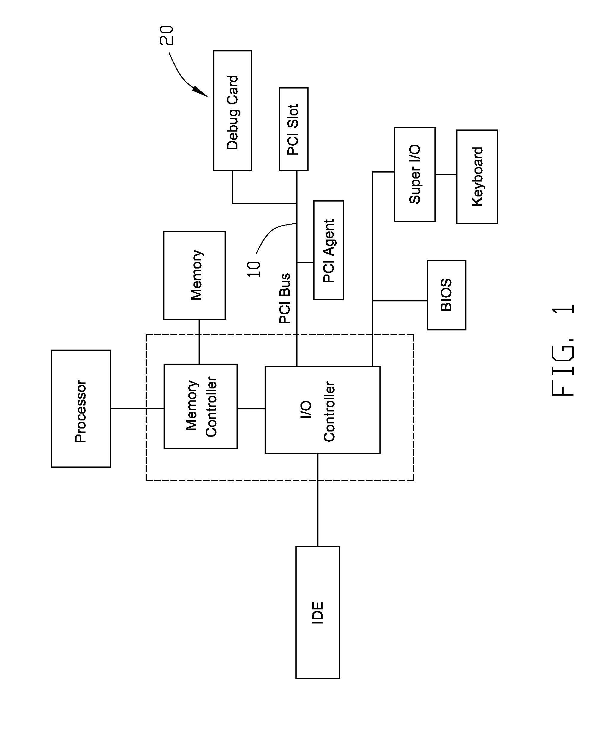
[0014]Referring to FIG. 1, a debug card 20 is connected to a PCI (peripheral component interface) bus 10 of a computer system.

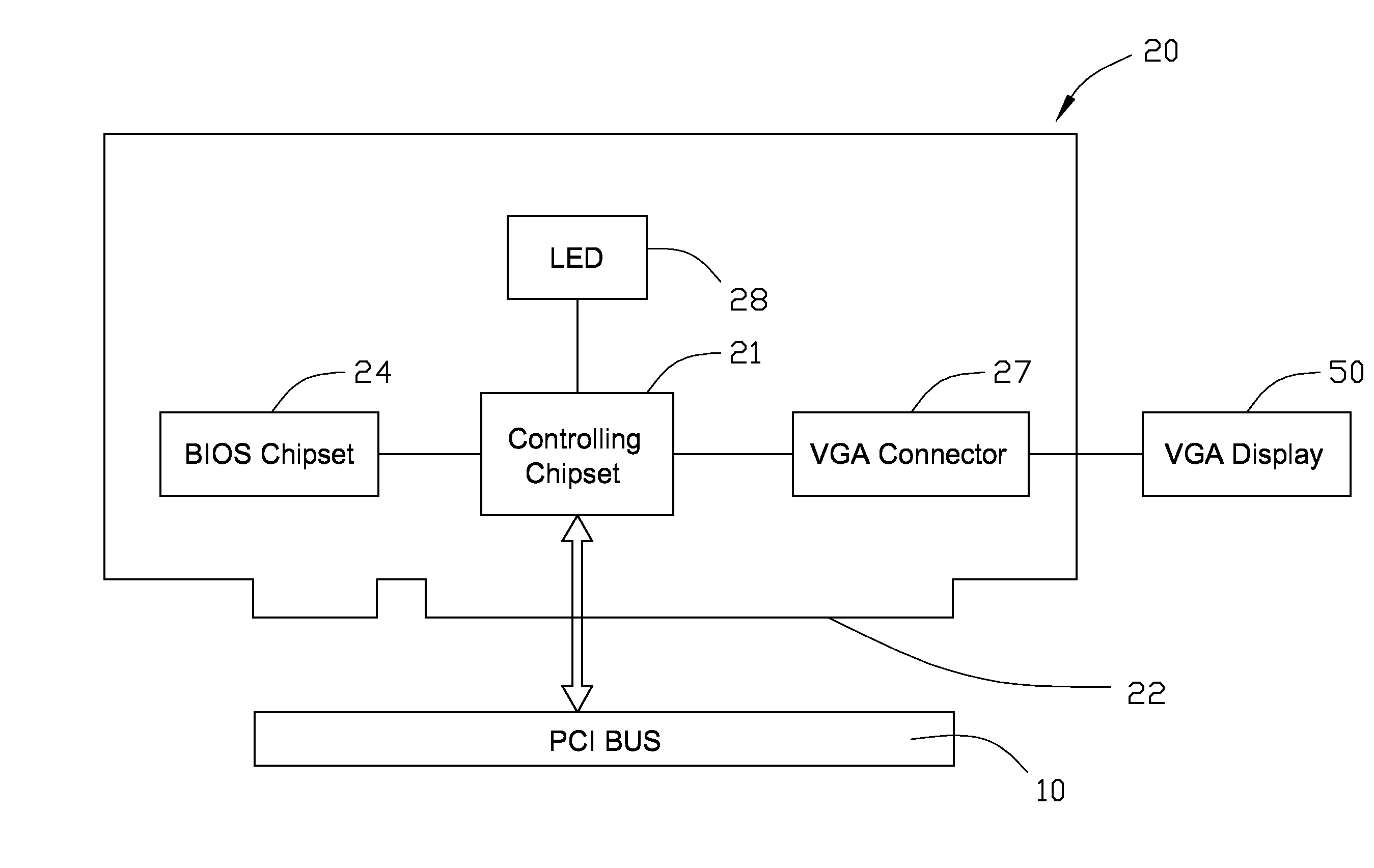
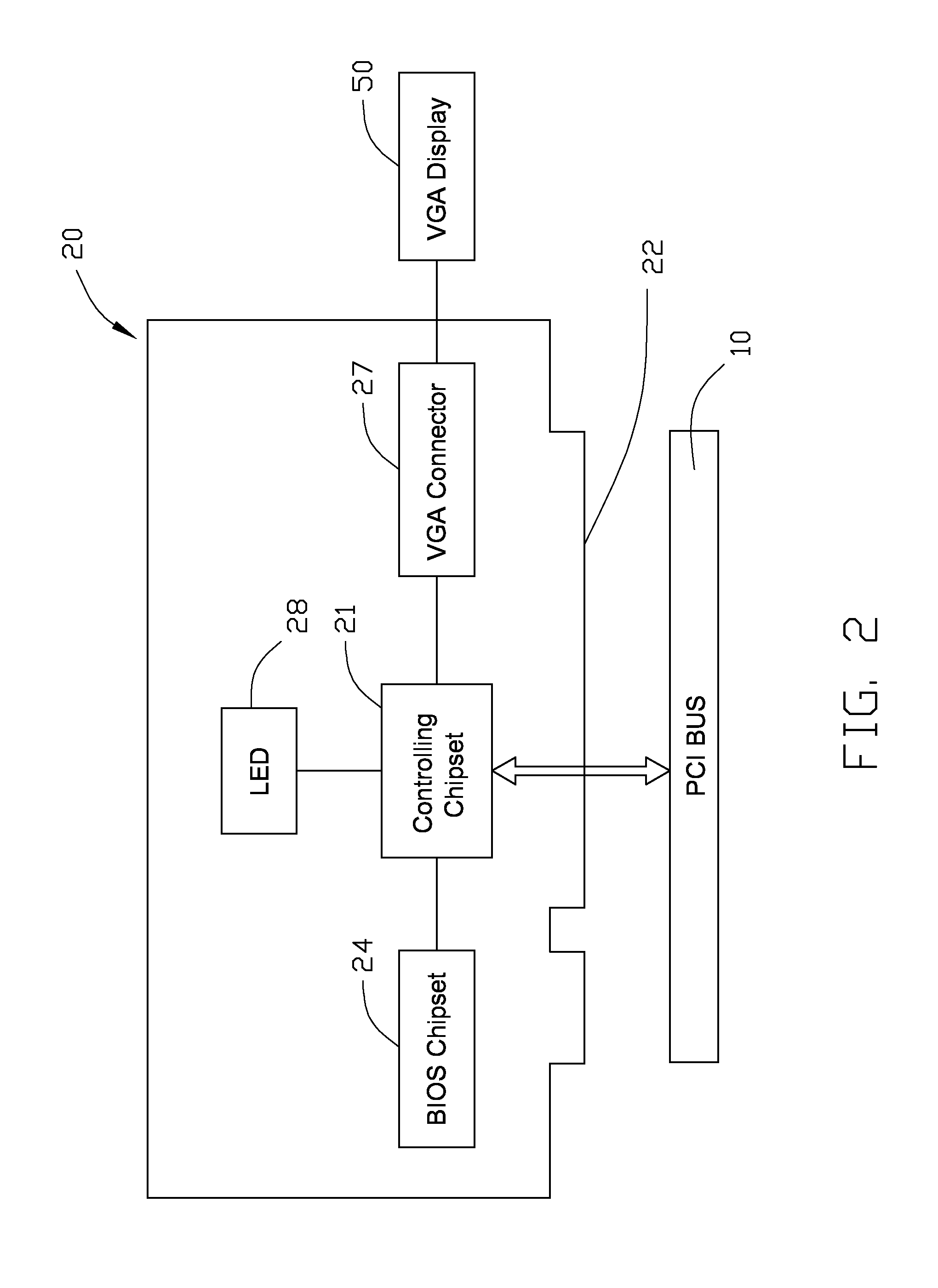
[0015]Referring to FIG. 2, the debug card 20 includes a controlling chipset 21, a BIOS (Basic Input Output System) chipset 24, a VGA (Video Graphic Array) connector 27, a plurality of seven-segment LEDs 28, and an edge connector 22 adapted for connecting to the PCI bus 10. The VGA connector 27 is connected to a VGA display 50.

[0016]FIG. 3 shows the time ordered diagram of the PCI bus 10. When the FRAME# signal changes from high to low, it signals the beginning of a PCI bus cycle. At this moment, the data on the AD (address / data) bus is the address that the PCI bus cycle wants to position while the data on the C / BE# (command / byte enable) is the command. Each device on the PCI bus cycle will perform decoding on the address and command to determine if it is a target device of the PCI bus cycle. If so, the device selection signal DEVSEL# is set to keep at LOW as ...


PUM


Abstract

A debug card includes a controlling chipset and a VGA connector. The controlling chipset includes a data storage module, a data transforming module, and a VGA controller. The data storage module stores data received from a computer system, which represents the status of the computer system. The data transforming module transforms the data and transmits the transformed data to the VGA controller. The VGA connector interconnects the VGA controller and a VGA display to display the data.

Description

BACKGROUND OF THE INVENTION[0001]1. Field of The Invention[0002]The present invention relates to debug cards, and more particularly to a debug card for debugging a computer system.[0003]2. Description of Related Art[0004]During a design phase, newly designed computer systems are not stable and reliable for mass-production, and include many firmware and software bugs. The newly designed computer systems require testing and debugging to improve their performance. A debug card is a very useful tool in the process of testing and debugging.[0005]A typical debug card includes a microcontroller, a storage device connected to the microcontroller, and means for connecting the debug card to a bus of a computer system. The debug card receives information via the bus, and records the information in the storage device. The debug card also includes a plurality of seven-segment light emitting diodes (LEDs) to represent the captured information. However, the seven-segment LEDs often are limited in ...

Claims


Application Information

Patent Timeline
IPC IPC(8): G06F11/07
CPCG06F11/3648
Inventor KAO, CHIEN-CHIHCHUNG, SHENG-PO
Owner HON HAI PRECISION IND CO LTD
Why Eureka
Try Eureka