Hip Protector

a technology for protecting pads and hips, applied in the field of hip protectors, can solve the problems of direct transmission of shear forces to this area of skin, inability inability to be in the correct position to protect the hip, so as to achieve the effect of effective protection of the hip and reduce the shear force on the skin

Inactive Publication Date: 2008-06-12
MINNS JULIAN
View PDF4 Cites 2 Cited by
  • Summary
  • Abstract
  • Description
  • Claims
  • Application Information

AI Technical Summary

Benefits of technology

[0017]By accurately determining the position of the region around the greater trochanter the device provides for effective protection thereof. The protector is equally useful for protection against falls and as a dressing to protect against pressure sores. By attaching the protector to the skin around the perimeter of the padded region, shear forces on the skin are reduced from the vulnerable area around the greater trochanter. Following hip surgery there is a need to monitor the heeling process of the wounds created by the surgery. The transparent nature of the padded region and the film used in attaching the protector to the leg allow the wound to be monitored without removal of the protector. One embodiment of the invention allows the protector to indicate whether the protector has been subjected to a force exceeding a certain threshold value. This is achieved by impregnating the silicone pad with frangible dye-filled capsules which fracture when subjected to a certain force.

Problems solved by technology

There are a number of problems with this kind of device.
They are unsightly, whether worn under or over the person's everyday clothing.
Such protective pads have a tendency to move with respect to the person's body, and may therefore not be in the correct position to protect the hip from injury (patient monitoring with one type of hip protector has found the device to consistently be positioned approximately 3 to 5 cm proximal and posterior to the centre of the greater trochanter whilst flexing from 0 to 90 degrees, lying down and moving about).
Another major problem with protective devices of the type described, is compliance, ie. individuals to whom the protective devices are prescribed do not wear them This may be because they are unsightly, or uncomfortable.
Whilst the hip protector described in WO 99 / 42011 attempts to distribute energy to soft tissue surrounding the greater trochanter, the fact that one part of the fastening means is attached to the skin over the greater trochanter means that shear forces are transmitted directly to this area of skin, which is often thin and weak.
In many accurate identification of the location of the greater trochanter by palpation is very difficult, even for trained medical staff.
Failure to correctly identify the position of the greater trochanter may lead to the hip protector being positioned such that an edge of the protector lies on or off the greater trochanter.

Method used


Image

  • Hip Protector
  • Hip Protector
  • Hip Protector

Examples


Embodiment Construction

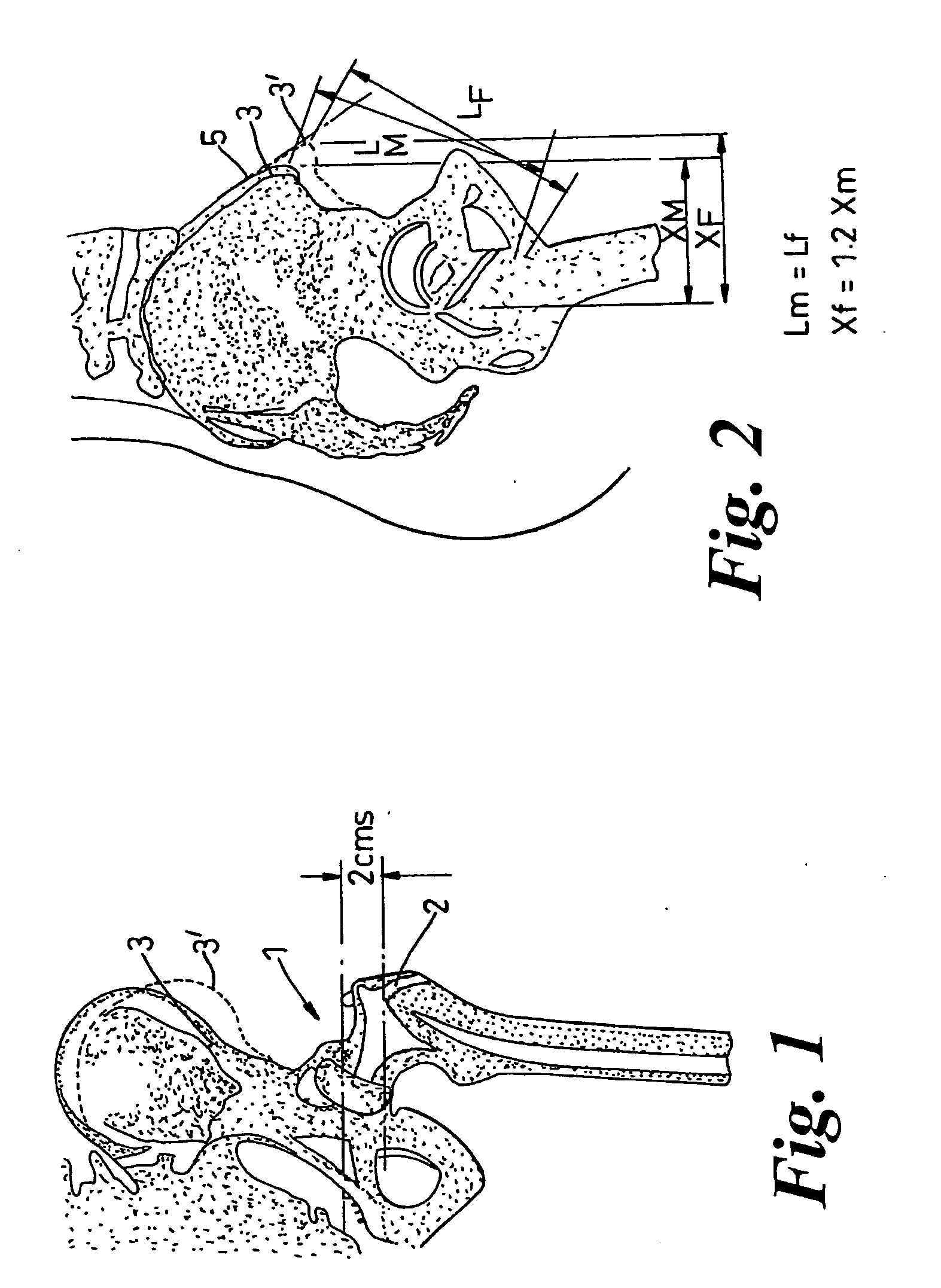
[0027]FIGS. 1 and 2 illustrate the part of the human skeleton including the hip 1. Hip protectors serve to protect the hip by dissipating energy away from the greater trochanter (GT) 1. In many individuals the GT 1 is very difficult locate by palpation. However, the anterior superior iliac crest 3 (for women and 3′ for men) is relatively easy to locate by palpation

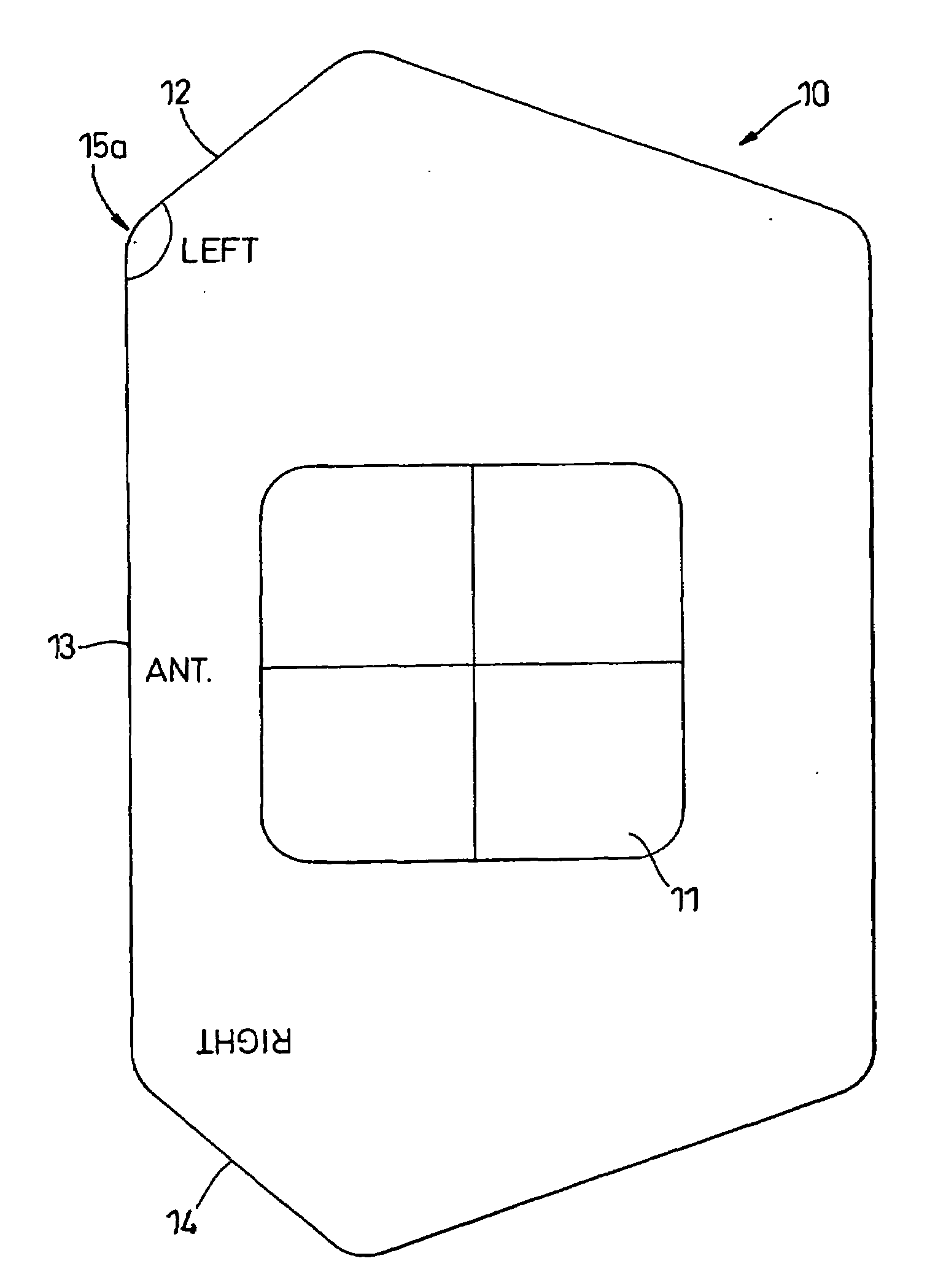
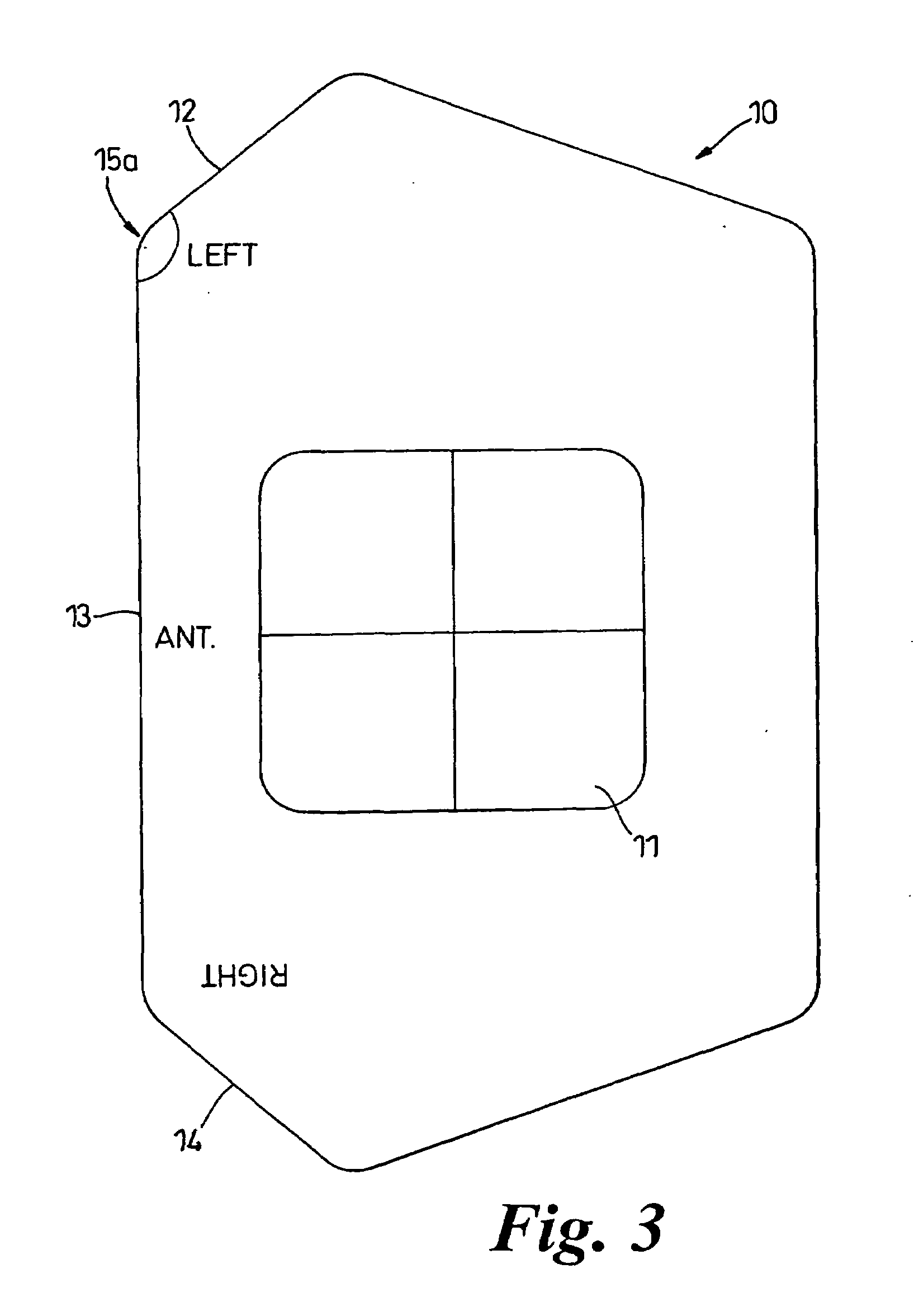
[0028]The template 10 illustrated in FIG. 3 can be used on either left or right legs and includes a central window 11, which when the template is correctly positioned defines the protected area around the GT. The window 11 is rectangular and is approximately 4.5 cm high×5.5 cm wide. The template includes short edges 12 and 14, each inclined to a long edge 13. As can be seen from broken line 5 in FIG. 2, the iliac crest is inclined to the vertical

[0029]When the ASIC has been located by palpation, the template 10 is placed on the side of the leg (see FIG. 4) with the long edge 13 substantially vertical. If the template 10 is...


PUM


Abstract

A hip protector comprises a padded region and an adhesive region surrounding the padded region, and a template, the template comprising a first element for alignment with an anterior superior iliac crest, a second element for alignment with a substantially vertical axis, and a third element which is substantially aligned with the greater trochanter when the first and second elements are aligned respectively with the anterior superior iliac crest and the vertical axis.

Description

FIELD OF THE INVENTION[0001]This invention relates to hip protectors, and in particular to a hip protector of the type that is attached to the skin covering the hip bone.BACKGROUND OF THE INVENTION [0002]In recent years it has become common to use padded devices to protect the hip. These devices are used for two different purposes. First, they are used to protect the hip from damage in the event of a fall, and second they are used to reduce the risk of pressure sores. In both cases these devices attempt to spread the forces that would otherwise act on the hip and pressure sores, to the soft tissues surrounding the hip where there is not the same degree of problem with tissue viability.[0003]Many devices in use consist of a protective pad that is held in place by a pocket in a garment, a belt and other straps. There are a number of problems with this kind of device. They are unsightly, whether worn under or over the person's everyday clothing. Such protective pads have a tendency to ...

Claims


Application Information

Patent Timeline
Patent Type & Authority Applications(United States)
IPC IPC(8): A41D13/00A61F13/00A41D13/05
CPCA41D13/0506A41D13/005
Inventor MINNS, JULIAN
Owner MINNS JULIAN
Why Eureka
Try Eureka